Hi. I was just thinking about full bridge topo, and found that i could be very easy to implement this on what i did...
Can someone confirm.
the added parts are in the shaded box. It just mimicks what the already amp does, but inverted...
Could it be that easy??
Forget the rest of the schematic, it is not updated.
If it works, it will require some modifications to the protection board and the output relay.
thanks
Pat Allen
Attachments
That's not going to work well if low harmonic distortion is what you're after, the 2nd half of the bridge is just 'floating' with no feedback whatsoever. You need at least a summing amplifier to add the two output signals together and make the signal single ended for you single-ended front-end.
Best regards,
Sander Sassen
http://www.hardwareanalysis.com
Best regards,
Sander Sassen
http://www.hardwareanalysis.com
Hi Pat,
I already gave you a hint:
Best regards,
Sander Sassen
http://www.hardwareanalysis.com
I already gave you a hint:
You need at least a summing amplifier to add the two output signals together and make the signal single ended for you single-ended front-end.
Best regards,
Sander Sassen
http://www.hardwareanalysis.com
Hi.
I have looked at my schematic and came to this conclusion:
To add feedback for the second bridge, it will require as much parts as to just build two completely separate amps...no gains there...
There is no way to keep the lower bridge totaly independant of the analogue signal...someone may want to argue about this.
i came on a app note from LT about a full bridge application with a LT1160/1162 (page 13). I studied it a bit.
I found two interesting parts, wich are LT1016 and TC4428.
I will continue to investigate anyway
thanks for any kind of inputs. I think it could be cool to have an open project for a full bridge D amp that uses the LT driver. I think it could end to something very interseting and simple.
Pat Allen
Hi Pat,
It is much simpeler, just use a single opamp as a summing amplifier and take the feedback off of the two outputs, the summed signal can then be fed back into the feedback loop as you normally would. Hence the summing amplifier replaces the resistor at the output that is now used in the feedback loop of the half bridge.
Best regards,
Sander Sassen
http://www.hardwareanalysis.com
SSassen said:Hi Pat,
It is much simpeler, just use a single opamp as a summing amplifier and take the feedback off of the two outputs, the summed signal can then be fed back into the feedback loop as you normally would. Hence the summing amplifier replaces the resistor at the output that is now used in the feedback loop of the half bridge.
Best regards,
Sander Sassen
http://www.hardwareanalysis.com
Summing amplifier????
Sum of both outputs is more or less zero!
I would guess a difference amp would be the right thing.
coming from you it sound so simple 
questions if you dont mind...
the resistor in the feedback loop sets the gain of the amp.
how the gain will be set if an opamp is inserted into the feedback loop? you sayd to remove the resistor feedback.
the feedback is taken before the lc filter, does it affect what you are saying? how the opamp will see the voltage swing?
i took what you sayd word to word and inserted it into my test sch.
I carefully inverted the added half signal of the bridge to the amp, hence the signal that goes to the inverted input of the opamp.
the value of the resitors are randomwly choosen for now.
thanks
Pat Allen
Attachments
ChocoHolic,
Correct, a common confusion of nomenclature, now where did I put my coffee? Pour me another!
Best regards,
Sander Sassen
http://www.hardwareanalysis.com
I would guess a difference amp would be the right thing.
Correct, a common confusion of nomenclature, now where did I put my coffee? Pour me another!
Best regards,
Sander Sassen
http://www.hardwareanalysis.com

... another simple principle was derived in this thread.
http://www.diyaudio.com/forums/showthread.php?s=&threadid=36349&perpage=10&pagenumber=11
Our class D amp guru's lead me step by step to an interesting design principle. (Thank's again!)
Last posting of page 11 shows how a full bridge could be driven with an unbelievable simple self resonating principle.
...did not try it, but it is still in my mind for my subwoofer...
Wow Choco, long time no see in class d land.
Pat, have a look at the Mueta schematic pdf at www.mueta.com you'll see an example of a differential amp in full bridge and I think you'll be able to see how the gain is set.
Pat, have a look at the Mueta schematic pdf at www.mueta.com you'll see an example of a differential amp in full bridge and I think you'll be able to see how the gain is set.
this is exactly what i did, except that i take the signal before the lc filter... (did you see my test sch?)
the mueta difference amp got like 1,12 gain...so they must compensate for the remaining wanted gain into the rest of the feedback loop...looks simple.
am i close or not?
the mueta difference amp got like 1,12 gain...so they must compensate for the remaining wanted gain into the rest of the feedback loop...looks simple.
am i close or not?
...I think the intension of classd4sure is:
instead of R13, R14 & C8 use the attached circuit.
This differential amp has a gain of 1/8.2, but two times
of the input compared to the former feedback network.
So the new feedback resistor has to be 4.1 times less than
the original (46k+1k), means 11.46k. I simplified it to 12k.
The low pass is performed also in my attached dif amp by the two capacitors.
Please be aware that all inconvinieces of feedback systems including insatbility can also happen in class D amps.
The active dif amp is adding another pole at high frequencies (depending on the chosen OP amp) and could theoretical make the frequency compensation of the entire amp more difficult.
cd4s:
...yes, I have been quite silent in any DIY topic for a long time. My bosses are keeping me busy...
Attachments
But ugh..!
It is quite ugly to run an OP amp with such massive rectangular signals. Behaviour of normal OP amps may differ very much from the ideal OP in this application.... and very fast OP amps might directly start to oscilate, because the dif stage has very low gain and heavy feedback.
Last but not least, the combination of 1k and 8k2 allows rail voltages up to approx. +/-40V, above you may drive the OP amp into clipping (also depending on OP voltage supply and OP amp type)....
If you want to use such a diff amp it is probably better to pick the feedback signal from behind the output filter. But be careful the output filter has quite a crazy phase shift behaviour and you would probaly have to redesign the entire feedback oscillation system....
I am sorry, but I feel things will remain difficult in realty, even if the basic approach seems simple and straight forward.
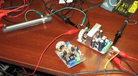
Hi, thanks for the comments.
I have put that aside a bit, i received my new pcb !!!
i assembled one, it fired up right away !!
my new protection feature works very well, the microprocessor monitor DC, pump up and pump down.
square wave at the output is super clean, no ring.
I have put that aside a bit, i received my new pcb !!!
i assembled one, it fired up right away !!
my new protection feature works very well, the microprocessor monitor DC, pump up and pump down.
square wave at the output is super clean, no ring.
Attachments
- Status
- This old topic is closed. If you want to reopen this topic, contact a moderator using the "Report Post" button.
- Home
- Amplifiers
- Class D
- Re-thinking of my D-amp...full bridge or not.