Hi All,
I just completed making a couple of mono'd T-Amps for what I hope is a fairly unique application (more on that later!). One channel works just fine, but the other one, after about 20 minutes or half an hour of operation, it stops playing with a none-too-loud crack or snap through its speaker (no noise from the amp from what I can tell). I let it set for a while, and plugged it in to my test speaker, and it played just fine! Further attempts to use end up with the same result.
Anyone have any idea what might be happening? Overheating? Bad connection? Combination of both? Shorting someplace? Does the 2024 have some sort of protection circuit that kicks in when something nasty happens? An upstream component?
If anyone has some ideas what it might be, or how I could go about inspecting these things, it would be appreciated. I only have a multimeter - no scope...
thanks,
Jeremy
Overheating
hmm, well I ran both boards in for a few months while I gathered ambition to do this, and I was using the same power supply then as I'm using now. But now I'm only using one channel, so I would expect the chip is even less stressed than it was... The supply is a 12V 3A regulated CB supply - I measured it as putting out just under 14V. I don't have the chip heatsinked, as the cases I'm using are very small, and there doesn't appear to be room.
The difference between the two channels cases, even though they appear identical is that the one that is cutting out appears to made from a higher density plastic. The non-working one's case is a little warm to the touch, and the working one is cold. I'll swap cases on them tomorrow (it's 2:30am out here in Halifax!) and see if this helps.")
thanks for the suggestion - I love your site BTW, panomaniac - the inspiration to try this came mainly from you.
Jeremy
hmm, well I ran both boards in for a few months while I gathered ambition to do this, and I was using the same power supply then as I'm using now. But now I'm only using one channel, so I would expect the chip is even less stressed than it was... The supply is a 12V 3A regulated CB supply - I measured it as putting out just under 14V. I don't have the chip heatsinked, as the cases I'm using are very small, and there doesn't appear to be room.
The difference between the two channels cases, even though they appear identical is that the one that is cutting out appears to made from a higher density plastic. The non-working one's case is a little warm to the touch, and the working one is cold. I'll swap cases on them tomorrow (it's 2:30am out here in Halifax!) and see if this helps.
thanks for the suggestion - I love your site BTW, panomaniac - the inspiration to try this came mainly from you.
Jeremy
Re: Overheating
That's pretty hot for these chips. 12V is safer. At that voltage I would certainly heatsink it. Check eBay for the ramdac heat sinks from seller "wluk". New Egg has some copper sinks that should be even better.
Do you have the new amps without solder slug under the chip?
Sounds like the problem.
Hey thanks! Glad to be of help.
Diomedian said:The supply is a 12V 3A regulated CB supply - I measured it as putting out just under 14V.
That's pretty hot for these chips. 12V is safer. At that voltage I would certainly heatsink it. Check eBay for the ramdac heat sinks from seller "wluk". New Egg has some copper sinks that should be even better.
Do you have the new amps without solder slug under the chip?
The non-working one's case is a little warm to the touch, and the working one is cold.
Sounds like the problem.
I love your site BTW, panomaniac - the inspiration to try this came mainly from you.
Hey thanks! Glad to be of help.
Re: Overheating
Do you know exactly what kind of plastic the two cases are made of? How are the binding posts mounted on the cases? Are they insulated from the case? If they aren't, try insulating them from the case or temporarily remove them from the case and see if the amp doesn't over heat then. Oddly enough, I ran into a similar problem some time ago with a certain plastic/rubber material that became more conductive as it was compressed. Using washers made of this material to insulate some binding posts from a metal chassis caused some issues that none of my EE professors could figure out... In the end the binding posts were semi shorting out to the grounded chassis through the washers. The case and the binding posts got warm too and amazingly the little SI board survived the whole ordeal (the sound did cut out and eventually stop and would come back after I let it cool down for a bit - sounds a lot like your situation).
That may not be the case with your chassis but who knows till you test it out.
Diomedian said:The difference between the two channels cases, even though they appear identical is that the one that is cutting out appears to made from a higher density plastic. The non-working one's case is a little warm to the touch, and the working one is cold. I'll swap cases on them tomorrow (it's 2:30am out here in Halifax!) and see if this helps.
Do you know exactly what kind of plastic the two cases are made of? How are the binding posts mounted on the cases? Are they insulated from the case? If they aren't, try insulating them from the case or temporarily remove them from the case and see if the amp doesn't over heat then. Oddly enough, I ran into a similar problem some time ago with a certain plastic/rubber material that became more conductive as it was compressed. Using washers made of this material to insulate some binding posts from a metal chassis caused some issues that none of my EE professors could figure out... In the end the binding posts were semi shorting out to the grounded chassis through the washers. The case and the binding posts got warm too and amazingly the little SI board survived the whole ordeal (the sound did cut out and eventually stop and would come back after I let it cool down for a bit - sounds a lot like your situation).
That may not be the case with your chassis but who knows till you test it out.
I experienced the same thing, one of my speaker binding posts (right +) was touching the metal casing, thus shorting with the ground. Try this test, get a multi-tester, put it in 1x resistance, connect to your speaker output binding posts and see if you have a short between + and -, same with the input rcas.
Thanks for the replies, guys.
So the first thing I tried was swapping cases - maybe the different plastic had an effect. That didn't seem to help.
Next, I picked up some copper RAM heatsinks at my local computer shop - the working channel sink barely heats up, but the channel that's cutting out gets too hot to touch.
Finally, I tried running the amp without the binding posts touching the case. While configured this way, I could no longer connect the amp to my main speaker (for reasons I'll get into in another post), and the amp was able to run for over an hour, but the heatsink was still cooking, though the speaker used was 8 ohm, whereas my main speaker is 4 ohm.
So I don't think this is a good result yet. I may as well describe everything I've done to the boards. (Just as a reminder, I'm using two boards in a mono configuration.)
1) I removed and bridged R01 to ground the left channel's input.
2) I tied together the red wires on the header so as to keep the amp always "on" when there was power.
3) I removed the mini-jack input so the board could fit in the case I'm using, and to make room for 4)
4) I put a 10 ohm, 1W resistor between the left channel's outputs.
5) I removed C3 so no signal would be going "backwards" through the input filter.
6) Between +ive input and -ive input, I put a 50Kohm resistor.
7) on the +ive input, I put a 27Kohm resistor, and then a 2.2uF cap - this went to the pad of R2.
8) The cap that's soldered across the speaker output in the original case was put much closer to the board because that's where it fit.
Any of that sound like an overtly bad idea?
To answer some questions - the boards are the newer ones without the solder slugs. When I unplug the amp from the speakers, and measure the resistance across the binding posts, I get about 12Kohms from both channels.
thanks,
Jeremy
oh - nono - I didn't connect to the board at R01 - it's connected at R1, like it should be.
oops - after looking at the schematic I notice I got something wrong.
I wanted to mono-block the amps, and use the right channel. So I should have grounded out the input to the left channel, which is R02. I don't think this grounding out step is really necessary - it was just a precaution, and the other one seems to be running fine this way. As R01 is "behind" C3 (which I removed) bridging R01 should have no effect whatsoever.
Both mono amps were constructed in exactly the same way... I know the boards weren't manufactured at the same time (I originally bought two T-Amps, and fried one of them with a faulty power supply, so I had to order another from another vendor), but they both say Rev A01. If I remember correctly, they were made within a month of one another - I can't see the date codes when they're in their cases. Anyone have anything else I can check? :-(
thanks,
Jeremy
As R01 is "behind" C3 (which I removed) bridging R01 should have no effect whatsoever.
[/B]
If you removed C3 then you may be shorting the 2.5V to ground. Did you check DC offset? If you have a resistance to ground, or a short, on the 2.5V side of the cap you'll get DC offset and that channel will use a lot of power.
On the unused channel you should just leave everything in place and tie to ground before or at R01. If you removed C3 and did any shunt to ground, that would not be good.
Maybe I didn't understand what you did. Can you post a sketch of your wiring diagram?
Wiring Diagram/Further Error?
Ok - here's the wiring diagram of the input of the right channel.
After reading another thread, I'm a bit worried that I may have put in my input cap backwards. Is this the case? Might this be the problem?
Also, I've measured the DC offset. In the cutting-out channel, it starts at about 60mV, and starts rising slowly... after a few minutes (didn't time it) it was at 400mV, and I shut it off. I checked the other channel, and this one started at about -60mV, and exhibited the same slow rising... hmm - yeah... this doesn't look good - I guess neither channel is working properly - as soon as the one channel has cut out, I turned off the (common) power supply right away. I would imagine the other channel would cut out as well if I would leave it on long enough.
Does this set off any warning bells? Could this be caused by a backwards cap? I only hope I haven't damaged my speakers too much...
Jeremy
Attachments
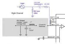
[7) on the +ive input, I put a 27Kohm resistor, and then a 2.2uF cap - this went to the pad of R2.]
You seem to be getting your channels mixed up.. R2 is the left ..
Also is the resistor or the cap' connected to the board? They should be connected as in your dia'..
The direction of the cap is dependent on the source voltage, over 2.5 V, + to source, under 2.5V, - to source.. I think?
Here is the original cct of the Sonic T..
Attachments
audio1st - you're right - I was confused about the channels. The pad of R1 is where I've put the input.
And it is indeed wired as I've drawn it - input RCA (with 50K to ground)->2.2uF->27K->R1 pad.
I've just measured my source - it puts out -6mV? Am I doing this correctly? I plug an RCA cable into the analog output of my DAC, and touch the positive lead to the centre pin, and the negative lead to the outside bit, right? Does the DAC need to be loaded or something before it puts out a higher voltage? Anyway, the manufacturer claims the DAC puts out "2.17V RMS at 1KHz Nominal (for 0dB digital level)", which seems about right. Which also means I've probably put the input cap backwards... Could this cause a drifiting DC offset?
Sorry for all of the newbie questions... :-(
thanks,
Jeremy
The rising DC offset is a new one to me, never seem that before. But I guess it could be caused by a reversed electro cap.
If you are using a polarized cap, then the + side goes toward the amp (R1) and neg does toward the input (DAC). So have a look at that cap.
Your diagram looks correct. Don't worry about any DC offset on the DAC, it will be blocked by C3.
If you are using a polarized cap, then the + side goes toward the amp (R1) and neg does toward the input (DAC). So have a look at that cap.
Your diagram looks correct. Don't worry about any DC offset on the DAC, it will be blocked by C3.
Ok, my cap was backwards. I've swapped it's polarity, and now we have something just as strange, but probably better.
The channel that was previously not working, starts at a DC offset of 60mV, and drifts downwards, seemingly settling at -4mV after about an hour of operation.
The channel that was previously deemed working starts at DC offset -110mV, and quickly difts to a fairly stable -113mV.
The only crazy guess I can come up with is that the cap throws some sort of field and this is scrambling the little brain of the poor 2024... Due to sloppy thinking and implementation of the first amp, the caps are oriented quite differently on each channel, but they sit more or less right below the 2024.
Two questions left: Is -113mV DC offset harmful to speakers (4ohm)? If so, is there any way of reducing it?
thanks,
Jeremy
I think they're working!
Well, I ran the amps for a few hours yesterday, and they didn't heat up much, and neither one cut out, so I'd say they're working now.
Unfortunately I wasn't able to choose which channel I was to use - it had to be the right channel. I'll post some pictures eventually.
Thanks for all the help!
Jeremy
- Status
- This old topic is closed. If you want to reopen this topic, contact a moderator using the "Report Post" button.
- Home
- Amplifiers
- Class D
- T-Amp Channel Cutting Out