Continuing a subject from another thread, about which is better, pre filter feedback (like ZAPpulse) or post filter feedback (like UcD, Icepower etc.). I don't want to risk thread jacking, so therefore this new thread.
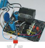
It is intended to show that both schemes are possible on almost any Class D platform using a simple switch and a few parts. Below you can see how it's simply implemented on a ZAPpulse 2.3SE. The parts values may differ on other Class D modules, but basicly it's the same circuit.
This way anyone can simply switch over, and compare the benefits of each type of feedback topology. I think that's the most honest way of advocating for a solution. Namely to let people check it out for themselves.")
Please note: this is not an official proposition of L C Audio Technology. They have nothing to do with it. It is just a proposition from one DIY'er to another. But it does work!
It is intended to show that both schemes are possible on almost any Class D platform using a simple switch and a few parts. Below you can see how it's simply implemented on a ZAPpulse 2.3SE. The parts values may differ on other Class D modules, but basicly it's the same circuit.
This way anyone can simply switch over, and compare the benefits of each type of feedback topology. I think that's the most honest way of advocating for a solution. Namely to let people check it out for themselves.
Please note: this is not an official proposition of L C Audio Technology. They have nothing to do with it. It is just a proposition from one DIY'er to another.
But it does work!Attachments
Lars,
As I already expressed in the other thread, what's the use of post-filter if you don't use it to allow for load-invariant behaviour of the amplifier? I'm sure lowering THD is a goal, but that isn't something I'd be too concerned about (if you've already got good scores in that department).
Furthermore the values you quoted for the ZapPulse modification are several magnitudes off any usuable value, just simulate a simple hyst. self. osc. with these values and you'll notice this modification does very little, if anything.
Best regards,
Sander Sassen
http://www.hardwareanalysis.com
Sander: aaaaaa sorry i don't think simulators are that useful. Fun to play with though. But for serious stuff i like to do real life measurements.
With regards to this:
.... i have no idea what you are talking about
Exactly, a good filter coil has much lower THD than the rest of the amplifier. So THD would not be a good reason to include the choke in the feedback control loop.
Hi John W:
Please give me a link, i'd like to see your findings.
Hi Workhorse
L C Audio was bought by an investment firm in 2002 after a chapter 11 bankrupcy. As a part of the deal i made a contract with them to work 3 years at a relatively low salary.
Now i have fulfilled the contract, and then left them in September 2005. Now i work independently and make a lot more than i did before.
However i still like to keep in touch with the audio industry, it's always fun, and i have many good friends here.
Lars
With regards to this:
Furthermore the values you quoted for the ZapPulse modification are several magnitudes off any usuable value......
.... i have no idea what you are talking about
I'm sure lowering THD is a goal, but that isn't something I'd be too concerned about (if you've already got good scores in that department).
Exactly, a good filter coil has much lower THD than the rest of the amplifier. So THD would not be a good reason to include the choke in the feedback control loop.
Hi John W:
have posted about my subjective results earlier
Please give me a link, i'd like to see your findings.
Hi Workhorse
L C Audio was bought by an investment firm in 2002 after a chapter 11 bankrupcy. As a part of the deal i made a contract with them to work 3 years at a relatively low salary.
Now i have fulfilled the contract, and then left them in September 2005. Now i work independently and make a lot more than i did before.
However i still like to keep in touch with the audio industry, it's always fun, and i have many good friends here.
Lars
Lars,
You'll be surprised as to how accurate simulators can be, LTspice has been a valuable tool for me in these past months, I would even go as far as to say that it has saved me months of prototyping, as the simulator showed me beforehand what areas were problematic and what to expect. Atual results measured on prototypes where a lot like those which I'd previously simulated.
If you can combine simulations (and a good understanding thereof) with actual measurements on a prototype you'll see that this speeds up the design process immensely. At least that has been my experience and that of many others, as some of the members here will be happy to explain to you.
As for the filter coil, and the output capacitor, it is a (reactive) combination that will interact with the reactive load that is the loudspeaker and hence represent a complex load to the amplifier that is not corrected for as the feedback takes place before the output filter, you can't correct that unless you apply post-filter feedback. I've done measurements on pre-filter class-D amplifiers that have clearly shown a rise in THD with higher frequencies (much like an ordinary dominant pole amplifier).
It is however perfectly feasible to keep the THD at a reasonably fixed level by applying post filter feedback, as done with UcD, or by applying both pre- and postfilter feedback on a non-UcD amplifier.
If you don't go through the trouble of doing that what exactly are the benefits of class-D? UcD is able to go places where it is difficult for any class-A/AB amplifier to go with its load invariant FR and THD. If other class-D topologies can't do this, where's the improvement? Then they're just a novelty, or a cost-saving solution, not a step forward, just another way of doing the same thing.
Best regards,
Sander Sassen
http://www.hardwareanalysis.com
It is however perfectly feasible to keep the THD at a reasonably fixed level by applying post filter feedback, as done with UcD, or by applying both pre- and postfilter feedback on a non-UcD amplifier.
If you don't go through the trouble of doing that what exactly are the benefits of class-D?
Well my real life work (not simulators) show that post filter feedback will not actually do much to improve THD.
But on the other hand you can also get a good low THD with pre filter THD (in real life i mean).
So i guess i just dont agree with you on this one.
It's not a matter of 'not going throgh the trouble' of implementing post filter feedback. My experience just tells me that post filter feedback has some inherent limitations that i don't want my amplifiers to have. Limitations that i can't see any way to work around without damaging the sound. As simple as that.
I know it can also be said that pre filter amps have inherent problems, like loss of gain at low impedances at 10-20 kHz. However i find it easy to get around these limitations without damaging the sound. (With a simple RC compensation filter).
UcD is by far not the only post filter feed back modules, there are many of them out there. And they all feature the same characteristics. And none of them are better in sound tests than a good pre filter feedback setup. Sorry.....
Anyway since there is so much prejustice around post filter feedback, and it's so easy to implement, i think my next generation of Class D amplifiers might have both options on board.
Hi Lars,
There's a BIG difference between implementing post filter feedback and a class-D amplifier having load invariant FR and THD behaviour. When implementing post filter feedback load invariant FR and THD behaviour are not thrown in for free, if that was the case we wouldn't be having this discussion. The real trick, which Bruno managed to pull off with UcD, is to make the performance of the amplifier independant of the load. Whether that's done with pre- or post filter feedback I really don't care, it is the end result that counts, wouldn't you agree?
As for an amp sounding good, I will simply not consider an amplifier that is known to suffer from a (clearly measurable) change in FR or THD with different loads to be a candidate in my listening room. Afterall I'm trying to reproduce the recording as accurately as possible and with the amplifier being such an important contributor I'd like for it to add or substract as little as possible from the recording. Aren't we all just looking for the fictious piece of wire with gain really?
Best regards,
Sander Sassen
http://www.hardwareanalysis.com
Anyway since there is so much prejustice around post filter feedback, and it's so easy to implement, i think my next generation of Class D amplifiers might have both options on board.
There's a BIG difference between implementing post filter feedback and a class-D amplifier having load invariant FR and THD behaviour. When implementing post filter feedback load invariant FR and THD behaviour are not thrown in for free, if that was the case we wouldn't be having this discussion. The real trick, which Bruno managed to pull off with UcD, is to make the performance of the amplifier independant of the load. Whether that's done with pre- or post filter feedback I really don't care, it is the end result that counts, wouldn't you agree?
As for an amp sounding good, I will simply not consider an amplifier that is known to suffer from a (clearly measurable) change in FR or THD with different loads to be a candidate in my listening room. Afterall I'm trying to reproduce the recording as accurately as possible and with the amplifier being such an important contributor I'd like for it to add or substract as little as possible from the recording. Aren't we all just looking for the fictious piece of wire with gain really?
Best regards,
Sander Sassen
http://www.hardwareanalysis.com
hi,
>UcD is by far not the only post filter feed back modules, there are many of them out there. And they all feature the same characteristics. And none of them are better in sound tests than a good pre filter feedback setup. Sorry.....>
my/our experience is the opposite
karsten madsen - cadaudio.dk/digiamps.com
km said:hi,
>UcD is by far not the only post filter feed back modules, there are many of them out there. And they all feature the same characteristics. And none of them are better in sound tests than a good pre filter feedback setup. Sorry.....>
my/our experience is the opposite
karsten madsen - cadaudio.dk/digiamps.com
Have you got any measurements on the digiamps that can back up your sound quality?
Lars Clausen said:
....
Anyway since there is so much prejustice around post filter feedback, and it's so easy to implement, i think my next generation of Class D amplifiers might have both options on board.
that would sure solve the argument.
So Lars, what are you up to on your next generation of Class D?
Hope you do SMPS also.
Lars,
Has anyone done a really high ripple current class D yet.
I did some experiements back a year ago with a hysteretic prefilter feedback design, and the results, when operating at load currents less than the ripple current, (okay 1/2 the ripple current) were amazingly good.
The IC I was using didn't lend itself to trying like stright up zero feedback modulator, but it seems like this might be a very interesting experiment.
When I hear about the zap pulse stuff, and your comments, I can't help but wonder what the topology is, and what ripple currents your running. Is it hysteretic? fixed frequency?
By the way, for others, the point of running high ripple current (a smaller value inductance and larger output cap) is that it minimizes the dead time error. This is becuase the inductor current always changes direction every cycle, thus when a switch shuts off, the inductor pulls it to the other rail right away and turns on the body diode of the other fet.
In my research on IC class D, I'd found that the root of most all the distortion was caused when the inductor current stops reversing in a cycle. Then, the switch node didn't change until the turning on fet pulled it down. The error can be modeled as a error pulse with the width equal to the dead time.
It seems to be analogus to Class A vs A/B. As usuall, there is a penalty, in that the peak currents of the fets is about double of a typical class D design.
A side advantage is your running a much smaller inductor. The LC Q is higher, but so what, its out of band. The frequency variations in the audio band are lower too.
Mike
I see the merits of a high ripple current setup. However you want to keep the ripple current well below the point where the flyback diodes are active. This means the higher ripple, the lower RDSon you need.
About ZAPpulse, i am sorry, at this point i am not in a position where i can publicise any details about that product.
All the best from
Lars
I am interested in this pre-post feedback debate. I have UcD 180ADs and a Sonic Impact. I really liked the Si sound and thought the Ucd would give the same sound with more power. Not so. The UcDs although good have very damped sound compared with the SI especially in the treble.
I am wondering if the differences in sound are solely due to the feedback differences or is it the variable freq used in the TriPath chip?
Another thing I have noticed about the SI sound is its "musical timing', the SI seems to be "always on the button" its sense of drive is quite addictive.
I am wondering if the differences in sound are solely due to the feedback differences or is it the variable freq used in the TriPath chip?
Another thing I have noticed about the SI sound is its "musical timing', the SI seems to be "always on the button" its sense of drive is quite addictive.
classd4sure said:They end up conducting anyway to some extent don't they?
Hi Chris,
Perhaps its possible to get the dead time such that the diodes never turn on, but I doubt it.
Having the diodes come on isn't a problem though.
Dead time is a don't care in such a design because all switch transitions happen when a switch shuts off, and when it turns on really is a much more minor even re distortion.
Mike
Fredex,
You should be aware that anything you do to a circuit will affect the sound. You cannot extrapolate sound down to one variable, unless there is just one variable. This is a problem that most of us do, we think that it must be this or that that makes for the difference in sound but actually it is a ton of stuff that affects the sound. I 've spent almost 30 years learning about execution and I am still learning (that is why I come here, in case someone discovers something new). So, if you want to see what an SI or UCD can really do then you need to tweak every dang thing for months and then compare. You still won't be able to tell what makes the different sound, however.
What Lars presents makes sense because you are only changing the feedback, no other parts or execution. No way you can compare two differently done technologies and draw any conclussion about why one sounds different than the other. Every little thing I do to the UCD modules: power supplies, damping, wiring, solder brands, etc. all change the sound. Sometimes dramatically. A stock UCD module hooked up in a normal way, does nothing much for me......modified....oh boy....serious fun.
Ric
I agree with your remarks about variables. However the only variable in my case is the amps and they do sound different (no surprise). It maybe the technology used or it maybe the implementation.
I don't know, but suspect it could be that the UcD uses feedback taken off after the OP filter, wereas the SI uses feedback taken off before the filter.
I haven't heard the ZapPulse modules but suspect they may sound more like the SI because of the pre-filter feedback.
- Status
- This old topic is closed. If you want to reopen this topic, contact a moderator using the "Report Post" button.
- Home
- Amplifiers
- Class D
- Post filter AND pre filter feedback..!