Hello Friends,
I have a problem.
I used http://users.ece.gatech.edu/~mleach/ece4435/f01/ClassD2.pdf
to design subwoofer bridge amplifier.
I used TL084 & IRF9540,540.
Used BC557&547 between OPamp & MOSFET.( eliminate for bipolar power supply ).
+/- 12 V & 45V used for power supply.
switching Frequency 30kHZ.
feed back freq abt 7.5KHz.
Used 2X150microH & 2X4.7microF for out put filter.
4.7microF in parallel with spk (10").
But amplifier cannot work well.
Input audiosiginal below 1V.
Traingle 3~4V.
Already check in Oscilloscope.
But spk output have +/- 1.5V P-P switching frequency exist.
for very small low frequency audio OK.
But increase volume it may occur blast sound.
So, what can I repair?
Components or Output Filter?
Sorry for my poor english.
Pls, advice me.
In myanmar component is very hard to find.
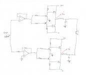
Your mosfet driver is WRONG. you have one fet with the gate voltage switching between 0v and ground!! The other FET will have a limited current switching it on due to the resistor.
Each fet needs a push pull supply to allow fast switching. But with the design there i am shocked that you even have a output at all!
Each fet needs a push pull supply to allow fast switching. But with the design there i am shocked that you even have a output at all!
Hello Friend,
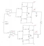
It is my new design.
But i tested already in old design.
Old design has a problem.
That is, two fet will be on when, no input switching signal.
So, I changed that design to new.
I will test the new design within 2weeks.
Pls, help me for new design.
It is my new design.
But i tested already in old design.
Old design has a problem.
That is, two fet will be on when, no input switching signal.
So, I changed that design to new.
I will test the new design within 2weeks.
Pls, help me for new design.
Attachments
Hello Friend,
Can I use that design for sine wave inverter?
I also interested in inverter design.
Pls, help me.
If you know the design of inverter, pls send to my email.
myanmar.digital@gmail.com
Thanks.
Myanmar.
Can I use that design for sine wave inverter?
I also interested in inverter design.
Pls, help me.
If you know the design of inverter, pls send to my email.
myanmar.digital@gmail.com
Thanks.
Myanmar.
Hi,
Try to get simulator. I use LTSpice that works as my expectation. Beside that try to follow lots of discussion about to build a DIY class D.
If you affraid you will not get the component, try first discrete design. I have been 1 year for learn the discrete class D. IMHO maybe you need long time too.
Good luck, welcome to this community.
Best Regards,
Kartino
kartino said:Hi,
Try to get simulator. I use LTSpice that works as my expectation. Beside that try to follow lots of discussion about to build a DIY class D.
If you affraid you will not get the component, try first discrete design. I have been 1 year for learn the discrete class D. IMHO maybe you need long time too.
Good luck, welcome to this community.
Best Regards,
Kartino
One year is not so long
") There's alot to know and we're all still learning.
There's alot to know and we're all still learning.Simulators are great for experimenting.
LTspice available here:
http://www.linear.com/company/software.jsp
sorry mate but your next circuit isnt going to work either!
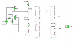
Heres the basic principal and i mean realy basic. It does not take into account dead time and has no filter. This will only work if the output of the osscilator is dual rail centered around 0v.
And a switching frequency that low will cause serious problems when trying to filter it out!
Good luck!
Heres the basic principal and i mean realy basic. It does not take into account dead time and has no filter. This will only work if the output of the osscilator is dual rail centered around 0v.
And a switching frequency that low will cause serious problems when trying to filter it out!
Good luck!
Attachments
Hi friend,
Input 500Hz means audio frequency or switching frequency?
Can you explain for your design?
What i need to learn?
Help me.
Because I am a starter.
I attached pdf.
In that pdf include FET control logic.
Can you design FET control logic for me?
Thanks.
Input 500Hz means audio frequency or switching frequency?
Can you explain for your design?
What i need to learn?
Help me.
Because I am a starter.
I attached pdf.
In that pdf include FET control logic.
Can you design FET control logic for me?
Thanks.
Attachments
Well im not designing the circuit for you but i will help you. My circuit is as simple as it can be. It has two identical power followers. One fed by a inverted input, the other by a non invering input. That then goes into a voltage follower which will increase the voltage fed into the input, this should be run off a power supply of about +-15V. As that is above the voltage that is needed to turn a mosfet fully on (i made a mistake putting +40v and 0v. That goes into a push pull follower that increases the current that can be fed into the gate of the FET. As gate capacitance cause fets to have a relitily low impenace at HF. That should also run off +_ 15v. That is then fed into the fets, one n type, one P type. So that One is on and the other is off at all times.
A filter is needed on the output of fets to prevent full power being used at all times. this is made using 1 or 2 inductors and capacitors. That feeds into a speaker.
A filter is needed on the output of fets to prevent full power being used at all times. this is made using 1 or 2 inductors and capacitors. That feeds into a speaker.
Hi Myanmar,
It is hard to tell you without you learn more and more.
Basically the people do designing from their brain when they have sufficient knowledge. For us, DIYer the short way to learn is learn other people design that already tested and works. For commercial you must find your concept to get patent, not other people concept.
In this Class D, even looked simple actually is not that simple. You must learn current transient behaviour at high speed.
Like you too I am also new comer and still learning. Chris is right, one year is not enough.
Regards,
Kartino
- Status
- This old topic is closed. If you want to reopen this topic, contact a moderator using the "Report Post" button.
- Home
- Amplifiers
- Class D
- classd woofer amplifier