Very nice job audio1st.
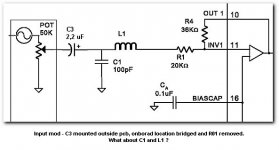
Based on previously postet schematic I 'moved' C3 and removed R01 acording to your diagram (see posted image below).
According to other threads it is common to move the inputs to the bridged C3-C4 and bypass both C1 and L1.
Being the nob I am I'm curious as to how this filter now work with the C1 and L1 still in place?
regards
HansR
Attachments
Hello HansR,
I have read on other posts of the other mod improving bass but the mid band loses out. Keeping the C1, L1 filter in may prevent this side effect. Panomaniac says, quote(The 100pF cap and the inductor are meant to drain off some of the RF that may be present on the input.) A slight treble roll off may be noticable but if it wasn't a problem in the unmodded Sonic, it shouldn't be a factor here. (it may be a good thing)?
I just thought it was an easier soldering mod than the other, leaves more SMD's intact and may even sound better.???
I'm sure this mod was suggested by SX881663 ( Roger) some time back.??
It sounds OK to me, but I am not as expert as most of you.
Just trying to help..
This is where I got the information..sx881663 said:http://www.diyaudio.com/forums/showthread.php?postid=571880#post571880
In this post (#21 in this thread) there is a drawing of the input circuit. As can be seen if you jumper out c3, c4 you will be connecting r01, r02 directly to the input. This causes a DC offset and will shut the chip down. The solution is to remove these resistors and jumper out the caps at the same time. Then put the quality 2.2uf film caps from the volume control wipers to the input connector on the board. The easiest way to do this is to find the wires from the volume control PCB that connect to the main board and cut them in the middle, splicing in the caps there.
Roger
WOW!!!! audio1st we are not worthy
Audio1st...you are a star!!!
Those pix are the best "explanation" I've yet encountered! They truly speak a thousand words! you've saved me a lot of headaches.
many regards
Eggz")
ps
Re: the stock pot...is it really that bad???? To me it feels nicely weighted and really well made. [anyone agree?] Should a variable resistor really make any noticable impact to the sound quality or am I just being naive? what is the governing factor?
Audio1st...you are a star!!!
Those pix are the best "explanation" I've yet encountered! They truly speak a thousand words! you've saved me a lot of headaches.
many regards
Eggz
ps
Re: the stock pot...is it really that bad???? To me it feels nicely weighted and really well made. [anyone agree?] Should a variable resistor really make any noticable impact to the sound quality or am I just being naive? what is the governing factor?
I asked a few of the experts about bypassing the input filters. I was very leary about removing the SMDs (so tiny). A quick solder tack job seemed so much easier. I was politely told that the filter is there for a purpose and shouldn't be removed. C3 and C4 really need to be replaced with higher quality caps of the proper values. I've successfully done two T-Amps now using this method and the results are worth it. The *very* noticable bass roll-off is gone. It sounds just great.
As far as the potentiometer goes - get yourself a 50k Alps RK27 Potentiometer (RK27112AS25C0A503) from TangentSoft. It's very smooth and well balanced. It works perfectly in this setup.
I've been using a 3 amp Astron and a 3 amp Radio Shack power supply with good results. I got the RS PSU in a closeout for $14. The little T-Amp likes an ample supply of electricity! I'm currently researching a 12v regulated power supply to build myself - more to come later........... (c8
Best regards,
PCH
audio1st said:Here is a Sonic T Amp, Bass Mod' dia'
Nice job, Audio 1st!
 You have done what I have been meanng for so long to get up on my site as the "stealth" input mod. No need to duplicate your efforts, I'll just link to your post.
Maybe you'll give me permission to use your diagram on my site? Full credit, of course.
I like this version, as it retains the input RF filters. Good for those big caps that might pick up RF noise.
panomaniac said:
Nice job, Audio 1st!
Maybe you'll give me permission to use your diagram on my site? Full credit, of course.
I like this version, as it retains the input RF filters. Good for those big caps that might pick up RF noise.
Hi Michael, is this exactly your 'Stealth' version or do you jumper the caps onto the board, replacing the originals rather than putting them before the filter?
panomaniac said:
Nice job, Audio 1st!
Maybe you'll give me permission to use your diagram on my site? Full credit, of course.
I like this version, as it retains the input RF filters. Good for those big caps that might pick up RF noise.
Thanks for your comments and you are welcome to use any of my pic's..
Panomaniac, after reading one of your replies on another thread, I did the filter bypass version on the 5066 mod thread..
I was concerned that the 100pf cap after the input cap would show a resistance of 80k at high frequency and raise the output voltage to the speakers, or is it not enough to worry about?
Barry...
Lostcause said:Hi Michael, is this exactly your 'Stealth' version?
Exactly the same. I just called it "stealth" because we were sneaking in ahead of the filter. Might as well use the filter if it's there. I won't affect the audio, but should clean up some noise.
I don't think the little 100pF cap will hurt the output. It certainly doesn't effect DC offset. As you know, R01/R02 must be removed, they will cause massive DC offset if used in this version.
I'll try to do a little more research on the effect of the 100pF cap. If anyone else does, please let us know. Maybe someone can spice model it.
I just saw that the 'stealth' version is up and i'd like to try it...however I have already done the 'Version 1' mod, removing R1 and R2.
So my question is can I still do the stealth version somehow, or will I need to put R1 and R2 back in (I already threw em away, or lost em)? Thanks
So my question is can I still do the stealth version somehow, or will I need to put R1 and R2 back in (I already threw em away, or lost em)? Thanks
jwb009 said:I just saw that the 'stealth' version is up and i'd like to try it...however I have already done the 'Version 1' mod, removing R1 and R2.
So my question is can I still do the stealth version somehow, or will I need to put R1 and R2 back in (I already threw em away, or lost em)? Thanks
I suppose you just need to use the resistors you jumped in with?
Un-solder from the caps and solder that end to the board to complete the circuit as it was? The traces/leads will increase the chance of RF pick-up but it may be OK?
DC Offset.
Since this thread has kind of turned into a modding thread on the t-amp, and someone brought it up above...
How can I lower the DC offset of the T-amp? I have a stock amp now, and the right channel is around 150mv and the left is around 45mv DC. Not a big deal with speakers, but I want to use the t-amp with my AKGK1000's, and I'm a bit concerned about exposing them to that much DC.
Have any of the mods above lowered the DC offset? What modification could I do to lower the DC offset?
Thanks for your help.
-Aaron.
noob<--
ok, so i got this t-amp and hooked it up and liked it. check. now i want to mod it so i search and find panomaniac's/audio1sts cool stealth mod. i picked it because it had the best drawing - honestly, no other reason.
so, i get myself some radioshack goodies, am already decent with a soldering iron just from fixing broken guitar pedals etc..and set to work.
so here are my questions. the capacitor number /value ratings confuse the bejeezus out of me. at some point i ordered some blackgate 16v2200uf caps. must have been drinking and ebaying again... anyway, i got those. then i see 2,2uf auricaps on audio1sts pic...now (and here's where i protect my head with both arms) are these the same value? if not will i screw things up if i use my blackgates? should i just order those auricaps i see in the picture?
also, i don't have a pot - yet - so i was thinking of running this thing wide open and letting my squeezebox do the volume control - which is what i do now with the unmodded t-amp. would i just go straight from the audioinput -> cap -> board following basically the same wiring?
and finally (i hope i'm not clogging this forum..seemed to me we were discussing the stealth mod...but i could be wrong) i didn't see in audio1sts picture that the speakers had the resistor thing wired between them like the original - is that on purpose or just out of scope of the mod? i went ahead and wired them on.
so i'm hoping that without any understanding whatsoever of the intricacies of electroengineering - i can just do some basic soldering of gizmos and doodads and enjoy some phatter bass...here's hoping!
--dij
ok, so i got this t-amp and hooked it up and liked it. check. now i want to mod it so i search and find panomaniac's/audio1sts cool stealth mod. i picked it because it had the best drawing
- honestly, no other reason.so, i get myself some radioshack goodies, am already decent with a soldering iron just from fixing broken guitar pedals etc..and set to work.
so here are my questions. the capacitor number /value ratings confuse the bejeezus out of me. at some point i ordered some blackgate 16v2200uf caps. must have been drinking and ebaying again... anyway, i got those. then i see 2,2uf auricaps on audio1sts pic...now (and here's where i protect my head with both arms) are these the same value? if not will i screw things up if i use my blackgates? should i just order those auricaps i see in the picture?
also, i don't have a pot - yet - so i was thinking of running this thing wide open and letting my squeezebox do the volume control - which is what i do now with the unmodded t-amp. would i just go straight from the audioinput -> cap -> board following basically the same wiring?
and finally (i hope i'm not clogging this forum..seemed to me we were discussing the stealth mod...but i could be wrong) i didn't see in audio1sts picture that the speakers had the resistor thing wired between them like the original - is that on purpose or just out of scope of the mod? i went ahead and wired them on.
so i'm hoping that without any understanding whatsoever of the intricacies of electroengineering - i can just do some basic soldering of gizmos and doodads and enjoy some phatter bass...here's hoping!
--dij
Hi Dijon,
Regarding those Blackgates, they are rated much much too high. The "uF" rating is more or less how much power they can store, so a 2200uF cap stores 1000 times as much as a 2.2uF cap. From what I can tell, if you used those Blackgates in place of a 2.2uF, you would blow up your speakers (someone correct me if I'm wrong). People have been reporting nasty turn-on thumps when using even 4.7uF caps, so...
As for the Auricaps, it needn't be them in particular - any decent 2.2uF cap should work. Personally, I'm using a Blackgate PK series cap (but if you use a polarized cap, make sure to point the "-" end towards the source - I wired mine up backwards with very strange results).
When it comes to voltage rating, you say you have 16V caps. That means that is the maximum voltage it is safe to apply to that cap. So if the circuit will see 10V, you can use a 16V cap. You could also use a 50V or a 100V no problem - it would just be a waste, as they tend to be more expensive. Usually though, when you expect to see some voltage X, you would use a cap that is rated a fair bit greater than X for safety's sake.
You're right about the volume pot. I'm not sure what a squeezebox is, but if it has a volume control, yes, you can just run it right into the T-Amp. It would go: input->cap->board, just as you said.
I'm not sure about the "resistor thing" you're talking about between the speakers. Do you mean the red 0.1uF film cap? If so, leave it in.
Jeremy
oops, my bad. those things on the speakers are capacitors..and i actually knew that one! as i said, i already connected them, so that's good to know, i'll leave them be.
as an aside the squeezebox is a digital audio player you can read about it at www.slimdevices.com it's my favorite music toy in the world..i have 4 of them..hence the need for all these tiny amps
so thanks diomedian for stopping me from putting those 2200uf caps in my squeezebox. i guess i'll try and get some 2.2uf - any online places that will sell me just 2 of them?
one final question regarding the pot if i decide to use one - my local radioshack only has single gang pots - no way these could be used right? the whole stereo thing?
man, i'm in deep water!
dijon
Sure you can get just two caps - The Parts Connexion sells nice high quality stuff:
http://www.partsconnexion.com/
(They're in Canada, but they sell in $US)
Also, Digikey sells just about everything except the "boutique" kind of parts that the Parts Connexion does:
http://www.digikey.com/
As for the pot, you _could use two mono pots, but then you'd have a tough time balancing the channels - it would just be a pain adjusting the volume twice. Both the Parts Connexion and Digikey sell a variety of audio pots - you just need to know which one you want. Digikey sells an overwhelming variety of everything. (If you want it, they probably have it, as long as you know what it's called
Jeremy
fried?
ok, after all that, got my parts etc..followed audio1sts diagram, solder all looks good (to me anyway), flipped the switch...zip. should i just scrap and assume i botched something (most likely removing and bridging those tiny caps). if anyone could tell me what to do with my circuit tester (like what setting, where to put the probes etc) i might be able to at least learn something from this. the good news is, i'm fired up enough to get another one of these things and just try again.
anyway, thanks in advance!
dijon
ps. there's power to the board as the led lights up and i get some clicks and pops as i push wires around but that's about it.
Re: fried?
Hi Dijon,
sorry to hear of your problem, any chance of some photos?
Did you remove R01 & R02 ? Seems strange that both channels aren't working..
You didn't need to remove caps C3 & C4, just blob, ( technical term ) some solder over them would have worked.
Your 2200uf Black Gates will be great for the power supply..
I don't think you could have done any damage and hope it is repairable. More info needed to help..
Barry.
dijon said:ok, after all that, got my parts etc..followed audio1sts diagram, solder all looks good (to me anyway), flipped the switch...zip. should i just scrap and assume i botched something (most likely removing and bridging those tiny caps). if anyone could tell me what to do with my circuit tester (like what setting, where to put the probes etc) i might be able to at least learn something from this. the good news is, i'm fired up enough to get another one of these things and just try again.
anyway, thanks in advance!
dijon
ps. there's power to the board as the led lights up and i get some clicks and pops as i push wires around but that's about it.
Hi Dijon,
sorry to hear of your problem, any chance of some photos?
Did you remove R01 & R02 ? Seems strange that both channels aren't working..
You didn't need to remove caps C3 & C4, just blob, ( technical term ) some solder over them would have worked.
Your 2200uf Black Gates will be great for the power supply..
I don't think you could have done any damage and hope it is repairable. More info needed to help..
Barry.
- Status
- This old topic is closed. If you want to reopen this topic, contact a moderator using the "Report Post" button.
- Home
- Amplifiers
- Class D
- Help Wiring a Replacement Potentiometer for Sonic T