I know the topic of Bridging the Tripath TA2020 & TA2024 has been covered ad nauseum here and elsewhere (can't be done), but there is no talk of Paralleling them. The chips are already Bridged and cannot be rebridged, understood. But Paralleling them should be possible to get almost double the power...also reducing the "work" required by each module (not that heat is an issue with these cool chipsets)
I can try Paralleling two TA2020 boards, as I have a few I can afford to mess with, but wondering if anyone has already attempted it?
I know the gainclone chips - LM3886, LM3875 - can be bridged(they are not already Bridged like the Tripaths), or paralleled, or both to double and quadruple the output power.
Any thoughts before I destroy two perfectly fine Tripath boards?
Interesting idea, but you wouldn't really get double the power unless you halved the load impedance. Paralleling them would keep the same output voltage swing but would be doubling (theoretically) the current capability. It would certainly help with some 4 ohm nominal drivers or even lower impedances.
Then there's the issue of where to parallel them: before or after the output filters? Since these amps don't seem to have a set modulation frequency, it would seem that you'd have to parallel them after the output filters. If you could somehow get them to synchronize their modulation frequencies with each other you could theoretically parallel the outputs before the filters and just use one output filter. Also, it might be helpful to add low impedance (maybe 1 ohm) non-inductive resistors in series with all outputs (both sides of each channel because the outputs are already bridged) to help ensure current sharing and to "cope" with the different DC offsets (each channel will surely have a different DC offset).
Then there's the issue of where to parallel them: before or after the output filters? Since these amps don't seem to have a set modulation frequency, it would seem that you'd have to parallel them after the output filters. If you could somehow get them to synchronize their modulation frequencies with each other you could theoretically parallel the outputs before the filters and just use one output filter. Also, it might be helpful to add low impedance (maybe 1 ohm) non-inductive resistors in series with all outputs (both sides of each channel because the outputs are already bridged) to help ensure current sharing and to "cope" with the different DC offsets (each channel will surely have a different DC offset).
Yep...
On a parallel arangement, the Output should not double (maybe 1.75x or so), but bridging should be very close to doubling (which we all know we can't do with the Tripaths)
The LM3886 Parallel schematic recommends a 3W .1 ohm resistor on each output before tieing them so the output channels don't fight each other.
Think I'll fry my boards if I try?
Re: Yep...
I actually meant to say .1 ohm in my above post but you could probably go a little higher (maybe even .5 ohm) if you had to. 2W would be a good safe rating for these power levels, but you could use lower rated ones. Twisting a bunch of Don't forget that you'd need 4 of these resistors, one for each side of the channel outputs.
I don't think you'll fry the boards if you try because the amps are fairly robust, but you never know. Regardless, definitely use a "disposable" speaker for testing! What load impedance would you use? 4 ohm nominal speaker? 4 ohm power resistor? If you do decide to go ahead with this please let us know the outcome!
john65b said:The LM3886 Parallel schematic recommends a 3W .1 ohm resistor on each output before tieing them so the output channels don't fight each other.
Think I'll fry my boards if I try?
I actually meant to say .1 ohm in my above post
but you could probably go a little higher (maybe even .5 ohm) if you had to. 2W would be a good safe rating for these power levels, but you could use lower rated ones. Twisting a bunch of Don't forget that you'd need 4 of these resistors, one for each side of the channel outputs.I don't think you'll fry the boards if you try because the amps are fairly robust, but you never know. Regardless, definitely use a "disposable" speaker for testing! What load impedance would you use? 4 ohm nominal speaker? 4 ohm power resistor? If you do decide to go ahead with this please let us know the outcome!
Brian's right about the chips being robust. I've thought several times that I killed one, but no - it lived. Even with 12 volts going into the right speaker wires.  Still alive!
Let us kow how it sounds. They should be combined post filter, as they are not synchronized (as mentioned above).
But what would be gained in a 4 ohm system? Lower output impedance is all, really, yeah? More current. Let us know if it works.
Still alive!Let us kow how it sounds. They should be combined post filter, as they are not synchronized (as mentioned above).
But what would be gained in a 4 ohm system? Lower output impedance is all, really, yeah? More current. Let us know if it works.
panomaniac said:I've thought several times that I killed one, but no - it lived. Even with 12 volts going into the right speaker wires.
I thought I might have been the only one to do this!!! I too was amazed the little guy fired right up after reconnecting the power wires properly

Done
Well, got all the soldering done and ran the TA202's in parallel. It didn't blow up. It did sound a bit louder...20 wpc to perhaps a 35 wpc??
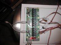
The boards I have have six independent channels and I paralleled four of the six...see pic below. The board also has two mini-pots to control gain on each channel. I noticed if one channel gain was lowered at high volumes, that would take that pair (the TA2020 chip) into fault mode, while the other 2 channels remained operating, and needed to push the mute button to reset the fault. Must have been a reverse voltage trip from the overpowering of the other 2 channels.
Anyway, it sounded just OK. Seems that the sound wasn't as precise as regular two channels straight up. But this could have been my power supply gasping for more amps - as I noticed the individual chanel LEDs would flicker on deep bass notes. Also could have been the .1 ohm 5 watt wirewound resistor (all I could find) on the four + outputs. The negative outputs were tied without resistors, as I don't think it was required. Maybe they are needed....
Anyway, if anything this is encouraging. I still beleive this can be done corrctly to increase the power of these chips by 50% - 75%.
Anyone else want to try and post results? I don't think it will harm your amp. If the TA2024 faults out, you should be able to just repower the unit up to reset the fault...
I have 10 1 ohm- 1 Watt resistors I can try on all positive and negative channel outs too. Maybe tomorrow...
I will repost the results.
Later
Well, got all the soldering done and ran the TA202's in parallel. It didn't blow up. It did sound a bit louder...20 wpc to perhaps a 35 wpc??
The boards I have have six independent channels and I paralleled four of the six...see pic below. The board also has two mini-pots to control gain on each channel. I noticed if one channel gain was lowered at high volumes, that would take that pair (the TA2020 chip) into fault mode, while the other 2 channels remained operating, and needed to push the mute button to reset the fault. Must have been a reverse voltage trip from the overpowering of the other 2 channels.
Anyway, it sounded just OK. Seems that the sound wasn't as precise as regular two channels straight up. But this could have been my power supply gasping for more amps - as I noticed the individual chanel LEDs would flicker on deep bass notes. Also could have been the .1 ohm 5 watt wirewound resistor (all I could find) on the four + outputs. The negative outputs were tied without resistors, as I don't think it was required. Maybe they are needed....
Anyway, if anything this is encouraging. I still beleive this can be done corrctly to increase the power of these chips by 50% - 75%.
Anyone else want to try and post results? I don't think it will harm your amp. If the TA2024 faults out, you should be able to just repower the unit up to reset the fault...
I have 10 1 ohm- 1 Watt resistors I can try on all positive and negative channel outs too. Maybe tomorrow...
I will repost the results.
Later
Attachments
Re: Done
 I tried to explain that in my posts above but guess I didn't make it as clear as I thought!
Thanks for sharing what you did so far! I bet it will sound better with equal resistors on ALL outputs - positive and negative.
They are needed because of the differential outputsjohn65b said:The negative outputs were tied without resistors, as I don't think it was required. Maybe they are needed....
I tried to explain that in my posts above but guess I didn't make it as clear as I thought!I would love to try this, but I don't have two spare amps to test with or the appropriate resistors.john65b said:Anyone else want to try and post results?
Thanks for sharing what you did so far! I bet it will sound better with equal resistors on ALL outputs - positive and negative.
Will re-try
BWRX --> You said four resistors in your previous post, and from the LM3886 datahseet outlining the parallel mode, you only need to put the four resistors on the four positive outputs and the neg outputs go to ground resistorless ...
I will try again with all eight leads resistored. Looks like I will have to do the 1 ohm 1 watt since I am 2 resistors short of the 8 required at .5 ohm 5 watts......
Think the wire wound resistors vs the Carbon types would lead to a major sound difference? After all, carbon types are used in the amps and the wire wounds are used in the crossovers, so tthey are both audio worthy...
I hope it sounds quite a bit better, as I was disappointed in the test sound quality...
More tomorrow...
Aloha Panomaniiac...
Nope, they came out of Video Game Kiosk. Actually, they were R&D fabs. Don't know if it ever flew or not. Got a bunch of them and a few 6 ch boards have inoperable channel/channels.
Put up a few for sale on Audiogon.
Preliminary tests confirm they put out more power than the TA2024 (duh), but lack some of the magic of the TA2024. We are still putzing with some of the power supplies (12 V 7Ah battery currently) and components (input/output caps to start) to see if we can regain that better soundstage and imaging from the TA2024.
From what I read, you have some profound knowledge/experience with these boards, any pointers? The SMD components on these bords seem to be laid out exactly like the schematic for the Tripath TA2020 datesheet, except they seem to have component values 10x bigger (ie 10 mH and the board has 100 mH inductors) - maybe 'cause of the six outputs sucking off the same power rails?
Anyway, your input is welcomed.
Rich - are you getting this?
BTW, transferred to Kapolei on Oahu in 1999 for work and lived there for 3.5 years... currently live in Utah...miss the beaches, Girls in skimpy bikinis, SCUBA Dives, Girls in skimpy bikinis, Kona beer and Volleyball on the beach, and yes, Spam Misubies (mainlanders will never understand the innate Hawaiian love of Spam - yum). Did I mention Girls in skimpy bikinis?
Mahalo
Re: Will re-try
I said 4 because I thought you'd only be testing one channel instead of a stereo setup. The LM3886 only need resistors on one output because they have single ended outputs. These Tripath chips need resistors on both outputs because they're bridged - the negative output is not grounded. This is just another example of how much punishment the chips can take!
john65b said:BWRX --> You said four resistors in your previous post, and from the LM3886 datahseet outlining the parallel mode, you only need to put the four resistors on the four positive outputs and the neg outputs go to ground resistorless ...
I said 4 because I thought you'd only be testing one channel instead of a stereo setup. The LM3886 only need resistors on one output because they have single ended outputs. These Tripath chips need resistors on both outputs because they're bridged - the negative output is not grounded. This is just another example of how much punishment the chips can take!
Whoops, my bad.
I will re-try tonight. I can always put these resistors at the speaker to make the wiring eaiser - no soldering at the board outputs, but double the wires.
If this arrangement works and sounds good, I will investigate paralleling my XR50 Panny outputs (party mode and reversed channels) to my Maggies to see if I can get 175wpc of pure digitally amplified love to them.
Whooo hooo...
After having all eight resistors on the outputs, the sound was a bit better, but I firmly believe my linear power supply is insufficient for these four channels.
I have two TA2024 amps and I will try them tomorrow, since power requirements would not be an issue here...
So far, so good.
I have two TA2024 amps and I will try them tomorrow, since power requirements would not be an issue here...
So far, so good.
john65b said:From what I read, you have some profound knowledge/experience with these board
Uh, well - yeah, I guess I do.
 Everyone needs a hobby, right?
they seem to have component values 10x bigger (ie 10 mH and the board has 100 mH inductors)
If they do, there is something very wrong. That would bring the filter -3dB point down by 10X, not a good thing. BTW, it's 10uH MICRO Henries, not milli. That would make a huge difference, too!
Yep, that's Hawaii, girls in bikinis, spam and coconuts. Gotta love it, brah!
As some else also replied, your must likely correct, these, the component values have to be correct...I must be getting my mili/micro mixed up...
Briefly tried the two Sonic Impact TA2024 boards paralleled, same difference. muddy, and incoherent. I may try again with a 1 ohm resistor on each output to see if that makes any diference...
more later
Briefly tried the two Sonic Impact TA2024 boards paralleled, same difference. muddy, and incoherent. I may try again with a 1 ohm resistor on each output to see if that makes any diference...
more later
Well, got all the soldering done and ran the TA202's in parallel. It didn't blow up. It did sound a bit louder...20 wpc to perhaps a 35 wpc??
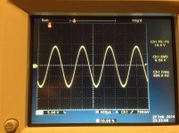
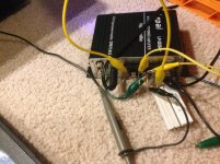
I just tried this last night and No. It doesn't work at all. You did not see any more power. The scope was floating and seeing the full output range into an 8 ohm resistor (2-16 ohms in parallel to handle the power). Stock supply was 13v, the bridged outputs generated a signal that swings about 20 volts (+10v from one half and -10v) from the other half..
RMS Power at 1Khz with the Stock Lepai LP2020+ with included adapter generates about 19.6v before distorting. Paralleling up the two outputs did nothing to the waveform.
I repeated the tests with a speaker and it was no different than the resistor.
The other thing I found was that you can only get about 19.6 pk-pk output = 6.93v RMS = 6.0Watts RMS into 8Ohms at ~1% distortion. This works great as computer speakers, but kinda sucks for my band gig rig..
Attachments
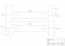
I think there is a way to bridge: bridged amps. It involves supply stacking...Or rather isolated supply stacking. The only assumptions is that the chips share/split the stack. The trick is common to TV transmitters. 50VDC supplies are stacked with there respective MOSFET amplifiers to generate killowatts into 50 ohm loads. I'm not suggesting you build a welder out of TA 2024 chips. But I am suggesting it might be possible to stack a pair for more voltage swing into 8 ohm loads.
Disclaimer. If you kill your friend/s don't blame me. It's just an idea I'm putting forth. I see ~$20 TA 2024 PCB at parts express you might give it a go. To improve crosstalk and dissipation (assuming it works) you might only use one side of each chip.
Disclaimer. If you kill your friend/s don't blame me. It's just an idea I'm putting forth. I see ~$20 TA 2024 PCB at parts express you might give it a go. To improve crosstalk and dissipation (assuming it works) you might only use one side of each chip.
Attachments
TA2020 to parallel correctly as Tripath intended needs a DC Servo circuit that monitors the DC Offset at the Outputs and corrects for this on the Inputs....
Failing to do this will lead to current flow from one channel to the other and power dissipation needlessly, even to the point of destruction of marginal parts....
Same applies for 2024
Somewhere I used to have the schematic from Tripath for exactly this. It used a pair of op-amps via LPF to the inputs....
- Status
- This old topic is closed. If you want to reopen this topic, contact a moderator using the "Report Post" button.
- Home
- Amplifiers
- Class D
- Tripath TA2024/20 Bridge/Parallel Config