Hi!
Having build an amp similar to the "amp30" at this page: http://listen.to/AUDIOEXPERIMENT I got curious and started looking for at way to use the very simple approach with higher power, only N-channel Fets and without ANY parts that are not common.
The result is shown in this post and there a few sim's are in the next post's.
It is only a model for simulation-purpose and therefore there is no bypass-caps and there is no input filter. The goal is to build this amp with normal leaded components and see if works. The best results be with SMD, but I want to keep it simple and see if a good PCB-design cant save som off the "damage" done by the leaded components.
The Fet's are to be IRFP264 as these seems to be very common and I have a lot of them. I dont have a PSpice model for them. Anyone?
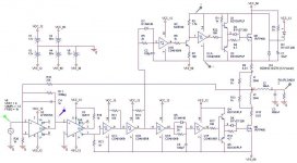
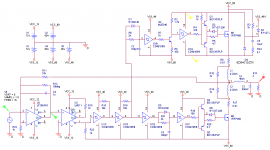
R9, R10, L1, R14, L3 and R17 simulate the PCB. - Or something like it..
U1A and U1F drive the BD's and at the moment of switching they have to deliver a high peak-current to the BD bases. Therefore The inverters should probably be made up of 3-4 inverters in parralel.
Deadtime is taken care of by the RCD-networks: D1, R5, C2 and D5, R19, C5.
All comments are velcome. My Questions (for now...) are:
1) What do you think of the driver-curcuit? I want to use discrete componets to make the the amp cheap and easy to build without any "special" parts.
2) I would like to add feedback after the filter but I hav'nt found a way around the phase-shift-problems?
3) If this amp is to be build as a bridge then only one modulator should be used, but then feedback is only taken from one part of the bridge. I have used this approach before and it works, but some sort of feedback from both sides of the brigde would be better.
4) The LM311 does a level-shift from +/-12V to -48/-60V.. is this ok?
5) Q2, R2 and R8 does the levelshift to the high-side-driver. I'm told that this part off the amp is critical and any better solutions are welcome.
6) If the output is ringing there should be added snubbers. What about diodes across each of the IRFP264's? I have some RHRG30120 (30A, 1.2kV, "Hyperfast"), but BYW29 might work?
That all for now. Sims and comments will be posted soon.
TroelsM
Having build an amp similar to the "amp30" at this page: http://listen.to/AUDIOEXPERIMENT I got curious and started looking for at way to use the very simple approach with higher power, only N-channel Fets and without ANY parts that are not common.
The result is shown in this post and there a few sim's are in the next post's.
It is only a model for simulation-purpose and therefore there is no bypass-caps and there is no input filter. The goal is to build this amp with normal leaded components and see if works. The best results be with SMD, but I want to keep it simple and see if a good PCB-design cant save som off the "damage" done by the leaded components.
The Fet's are to be IRFP264 as these seems to be very common and I have a lot of them. I dont have a PSpice model for them. Anyone?
R9, R10, L1, R14, L3 and R17 simulate the PCB. - Or something like it..
U1A and U1F drive the BD's and at the moment of switching they have to deliver a high peak-current to the BD bases. Therefore The inverters should probably be made up of 3-4 inverters in parralel.
Deadtime is taken care of by the RCD-networks: D1, R5, C2 and D5, R19, C5.
All comments are velcome. My Questions (for now...) are:
1) What do you think of the driver-curcuit? I want to use discrete componets to make the the amp cheap and easy to build without any "special" parts.
2) I would like to add feedback after the filter but I hav'nt found a way around the phase-shift-problems?
3) If this amp is to be build as a bridge then only one modulator should be used, but then feedback is only taken from one part of the bridge. I have used this approach before and it works, but some sort of feedback from both sides of the brigde would be better.
4) The LM311 does a level-shift from +/-12V to -48/-60V.. is this ok?
5) Q2, R2 and R8 does the levelshift to the high-side-driver. I'm told that this part off the amp is critical and any better solutions are welcome.
6) If the output is ringing there should be added snubbers. What about diodes across each of the IRFP264's? I have some RHRG30120 (30A, 1.2kV, "Hyperfast"), but BYW29 might work?
That all for now. Sims and comments will be posted soon.
TroelsM
Attachments
Simm of the amp
Here's the first set of sim-result's:
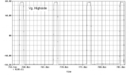
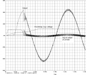
The amp dos'nt osc at startup but it starts after ½ a period when the signal goes negative. I don't think this is a problem.
At high pos. voltage at the output the freq drops very much. Hav'nt figured out why. It's very late 4.08 in the morning). I´m not gonna work on that now.
TroelsM
Here's the first set of sim-result's:
The amp dos'nt osc at startup but it starts after ½ a period when the signal goes negative. I don't think this is a problem.
At high pos. voltage at the output the freq drops very much. Hav'nt figured out why. It's very late 4.08 in the morning). I´m not gonna work on that now.
TroelsM
Attachments
Hi,
Excellent effort.
My only comments at this time are, remove or lower R22 and R17 if you really want the current to flow to the BD's.
There's a few projects around which answer alot of your questions, dig up the "reference design" thread it's too full of good info to ignore.
You're drivers will hold a small amp together, should be fine for the experiments you're doing, that doesnt' mean that they won't need all kinds of tweaking though, parallel as many inverters as required to get the job done.
3. correct.
4. I highly doubt it, check the data sheet look into AC coupling or level shifting properly. Was smart to ask though, simulators aren't all telling.
5. It is. Opto or magnetic coupling are options, it'll depend if your current solution is OK or not.
6. Diodes across the fets aren't mean to cure ringing, they're meant to prevent the body diode from becomming saturated which will then cause some wicked shoot through/dissipation/failure. You really need the right diode for the job, schottky's.
Keep at it, this is great stuff.
Chris
is this really that simple? it looks pretty complicated to me.
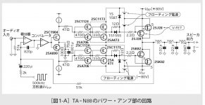
if you want to stay all discrete, you may want to look into TA-N88, a sony digital amp from years ago - it actually looks quite similar to your design.
a few questions - I am learning Class D myself as well:
a) why not use a gate driver, like ir2011 or the lm chip I mentioned in another thread? what is the advantage of having all discrete gate drivers?
b) why use the comparator for level shifting? wouldn't a simple transistor do that just as well?
TroelsM said:Hi. Spanks for the fast answer.
It's getting too late here, but one thing: Can you suggest any improvements to the drivers? If its not gonna ruin the whole keep-it-simple-and-cheap-thing, then any ideas would be welcome.
TroelsM
Nah I'd say start with that and see how it works. Simplest is best to start with and that seems fairly simple.
When you do it with discretes like that you're going to learn alot so keep at it. When you want better there's already circuits on here that will teach you even more, and meet all your criteria. Lucky you
")
Regards,
Chris
I don't own the TA-88N schematic I only know its block diagram (after which I developed my first class-d amps). And I might find out the patent number again.
I also once used BD135/6 as drivers that were themselves driven by 4049 CMOS drivers.
This topology was actually quite fast but I started to experiment with the fist IR2110 as soon as it came out.
Specialised driver ICs are indeed simpler to use but the ubiquituous BD transistors are more easily obtained of course.
Regards
Charles
I am not sure at all about the level-shifter implemented inside the LM311...
Please have a look at another thread that is very active lately : "how to fix this sch". I proposed a simple topology for level-shift, gate drive and bootstrap. It hasn't been tested but should work better or worse. It is in fact the individual stages are very similar to your proposal, but it is simpler, and it uses a level-shifter based on a transistor after the PWM modulator.
Have you implemented that sch in real life?
Best regards,
Pierre
I'm not going for an discrete solution but a cheap and easy one. The inverters are dirt-cheap and do a nice job at "cleaning" the signals.
The schematic hav'nt been implemented yet, but one of these days it will be.
The levelshifter from the LM311 will be fixed soon.
I'll have a look at some of the other threads (again) and return with the updates to the schematic
TroelsM
The schematic hav'nt been implemented yet, but one of these days it will be.
The levelshifter from the LM311 will be fixed soon.
I'll have a look at some of the other threads (again) and return with the updates to the schematic
TroelsM
Re: Simm of the amp
You're right, it isn't a problem..... in simulation
I think you'll find it will be in reality. All it takes is a simple circuit to precharge it, and a slightly more complex one to provide a delay at turn on to ensure it has the time to fully charge.
Some level of frequency modulation is natural in most self oscillating amps but it shouldnt' drop too much. That's why it's good to switch at 500kHz instead of 320kHz. Then you dont' really care all that much if it drops down even 150kHz.
There may be ways of limiting it with tweaking feedback as well. I couldn't tell you how though. Maybe Charles can.
Regards,
Chris
TroelsM said:Here's the first set of sim-result's:
The amp dos'nt osc at startup but it starts after ½ a period when the signal goes negative. I don't think this is a problem.
At high pos. voltage at the output the freq drops very much. Hav'nt figured out why. It's very late 4.08 in the morning). I´m not gonna work on that now.
TroelsM
You're right, it isn't a problem..... in simulation
I think you'll find it will be in reality. All it takes is a simple circuit to precharge it, and a slightly more complex one to provide a delay at turn on to ensure it has the time to fully charge.
Some level of frequency modulation is natural in most self oscillating amps but it shouldnt' drop too much. That's why it's good to switch at 500kHz instead of 320kHz. Then you dont' really care all that much if it drops down even 150kHz.
There may be ways of limiting it with tweaking feedback as well. I couldn't tell you how though. Maybe Charles can.
Regards,
Chris
Attachments
Pierre: If this is the sch youre referring to (http://www.diyaudio.com/forums/attachment.php?s=&postid=748810&stamp=1129882065). Then I don't get it... have you simulated it? The level at the base, at top BD139/BD140's wont ever be higher than approx 5V and it should be min 56v+12v = 68V.
Next point: At the moment of switching the BD's have a very low current gain and the base-curent will be pretty high. In your sch the basedrive wont ever be very high becurse of the 1k resistors.
Thats why I use the 40106-inverters. They give a clean switch and a high "current-gain" ast high Freq.
Please do coment.
TroelsM
Hello all,
Interesting thread, can't wait to see how it developes. What frequency are you planning on running this amp at? I can't see the totem pole driver arrangement going too fast, also why the multiple dead time? One on the fet gate, one in the logic?
You all seem to be using the same schematic/sim software. Which is it?
Keep up the good work!
Mad.P
- Status
- This old topic is closed. If you want to reopen this topic, contact a moderator using the "Report Post" button.
- Home
- Amplifiers
- Class D
- The cheap simple ClassD