I have solved the offset issue. At least in the simulations, it works perfect. You simply have to add a resistor from - INPUT to VREF, with the same value as the feedback resistor (100K). This way, the feedback signal has an added 2.5V so the output is now centered at 0V (excluding opamp offset errors as usual).
Output DC offset can be finely adjusted by making that resistor adjustable. I attach an updated proposal of the complete Class-D amp.
Gain is 20V/V (26dB). With the components used in the simulation, freq. response at -3dB is from 14Hz to 34KHz, but the simulation doesn't include the output filter nor accurate modelling of the error amplifier so there results should be verified experimentally.
The compensation network may need to be adjusted, but that won't be difficult if NFB is taken before filter.
With the proposed Rt and Ct values, switching frequency is around 175KHz (using a SG3524).
Attachments
Charles.
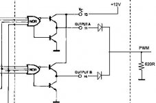
The sch is for a SG3525 that has totem-pole outputs.
IMHO the diodes are ok; this is how I see it: Each totem-pole output stage of the SG3525 will drive 12V when active, and pull to 0V when inactive, so the diodes are there to avoid that any transistor pulls down to 0V, blanking the output at any time (as two outputs are never active simultaneously).
BUT: you are right in that it won't work: a pull-down resistor is needed from base of Q1 to GND.
Is this ok? (I may be wrong, I am writing and drawing as the ideas come to my mind, so plese help debuggin it)
Then it is ok as I have drawn it, right? (with the pull down, of course)
I attach a drawing of the internal output section and how it is wired. This way, PWM is not inverted. So it attacks the level shifter, which inverts and hence must go to the LS driver.
But I am still not sure about how it should be done with a SG3524 for not-inverted PWM output ¿¿¿???
I attach a drawing of the internal output section and how it is wired. This way, PWM is not inverted. So it attacks the level shifter, which inverts and hence must go to the LS driver.
But I am still not sure about how it should be done with a SG3524 for not-inverted PWM output ¿¿¿???
Attachments
Is the partial schematic shown from a 3524 ? If yes you can ground the middle of both totem poles and tie the collectors of the upper transistors together. Said collectors would then be connected to the base of the voltage-translator transistor and a pull-up resistor to +12V should also be in place. But phase would be inverted in this case which can easily be solved by changeing the inputs of the mosfet driver IC.
Regards
Charles
Edit: didn't notice that the collectors are already connected together !
Regards
Charles
Edit: didn't notice that the collectors are already connected together !
No, Charles. That's for a SG3525.
SG3524 has "uncommitted" transistors (only one per output as opposed to the totem-pole output of the SG3525).
Anyway, I think that this is almost solved. This afternoon I will try to connect a couple of diodes to a SG3525 test board I made some time ago, and let's see how the PWM looks like.
As for the NFB network: I think it should be almost ok this way, provided that it is taken before filter, what do you think, Charles?
It may work up to 150-200KHz, that should be ok for decent full range quality.
Thanks
I would recommend that you started with a half-bridge and then connect two of them in bridge mode.
Yes, I can do that, if the full bridge mode is too difficult for real amp. Chris also said that making full bridge is difficult, making 2 halfbridge in bridge mode is OK for me, as long as the rail bus pumping will not existed.
About the IR2111 driver, be prepared to have quite high switching losses, due to its small drive capability that will lead to slow rise/fall times unless you use small or low-capacitance mosfets. IRF640N is a good start. The only advantage of that chip is simplicity.
If the full bridge (or 2 bridge half ones) can be done, I will do it with only +/-30V rail. That is the same with +/-60V half bridge, isn't it?
I planned to use IRF540 to keep the cost down. It is not OK to use IRF540?
The coil is a drum core, isn't it? I started also with one of them from Wilco, with good results, although a iron-powder toroid core is better.
How about air core inductor? Is it OK to use this too? Like the ones for passive Xover?
In a 2 x half-bridge in bridge mode you won't have bus-pumping.
In fact, if you use +/-30V rails, provided that you won't get 100% modulation index with the SG3524/5, you will get around 54Vp-p or double of that (108Vpp) in bridge mode. With a 8ohm load, that's about 180W. But you can go to a higher voltage, say, +/-40V, and you can get around 325W into 8 ohm.
Of course, you can go to 4 ohm, but in that case each stage "sees" 2 ohm, so for +/-30V you will get a peak current of about 15A, and a total power in bridge mode of around 360W/4ohm (say, 450W with +/-40V rails).
The IRF540 (better, IRF540N) mosfets seem ok for your application as they have not very high gate charge, low Rds(on) and high dV/dt rating.
About the inductor: the problems with air core inductors are: higher conductivity losses (you need a lot of turns and hence high resistivity for a given inductance), and radiated EMI. You should use a drum core or, better, a toroidal one.
Best regards,
Pierre
After doing some testing with SG3524/25, I have found them to be a bit too slow in terms of operating frequency, minimum dead-time and rise/fall times.
I think that a great improvement would be to use UC3825 chip, that is very similar in operation, but much faster. Even the error amplifier is faster (6-12MHz vs. 1MHz GPBW, 6V/us vs 0.5v/us SR). This would allow full-range operation with very good quality in my opinion.
Cost is higher, of course, but not so much ;-)
BTW: Please have a look at this reference: it details some alternatives for the high side driver, all of them discrete. The low side one is straightforward, so if we could do it without the IR/HIP/National chips, that would be nice.
The third alternative seems better, although it may need some tweaking:
http://www.innovatia.com/Design_Center/High-Side Drivers.htm
Pierre said:Charles.
The sch is for a SG3525 that has totem-pole outputs.
IMHO the diodes are ok; this is how I see it: Each totem-pole output stage of the SG3525 will drive 12V when active, and pull to 0V when inactive, so the diodes are there to avoid that any transistor pulls down to 0V, blanking the output at any time (as two outputs are never active simultaneously).
BUT: you are right in that it won't work: a pull-down resistor is needed from base of Q1 to GND.
Is this ok? (I may be wrong, I am writing and drawing as the ideas come to my mind, so plese help debuggin it)
Hi Pierre,
I"ve been toying this kind of circuit for about 7 months now using sg3525 mounted on solderless breadboard and it sounds good with nice bass and treble when driven by my son"s Sony discman via a coupling cap on pin 9 directly, but when I use its own comparators input pin 1 or 2 given with correct bias network, the bass and treble disapear. the reason is just because of the compensating .01uf cap connected to comparators o/p pin 9(as per sugested by chip maker). Removing this cap creates erratic oscillation in the o/p in which my scope cant follow the waveform.
BTW the 2 diodes in your o/p (pin 14 and 11) is correct followed by a pulldown resistor. My prototype uses 220ohms 2watts on that resistor. the purpose of this 2 diodes is to "source" during logic 1 of either o/p then the 220ohms resistor will handle the "sink" because diodes dont have sink capability
BTW, I use my big Pioneer head phone in listening b'coz I dont have any power Fet lying around yet.

cheers
ledmania
Pierre said:After doing some testing with SG3524/25, I have found them to be a bit too slow in terms of operating frequency, minimum dead-time and rise/fall times.
I think that a great improvement would be to use UC3825 chip, that is very similar in operation, but much faster. Even the error amplifier is faster (6-12MHz vs. 1MHz GPBW, 6V/us vs 0.5v/us SR). This would allow full-range operation with very good quality in my opinion.
Cost is higher, of course, but not so much ;-)
htm[/url]
Hi Pierre,
You are correct, sg3525 is slow on its rise/fall times but comparing its response time to other discrete devices, this chip is still more robust than some discretes counter part. I can say this b'coz of its interesting features inside the package like soft start which avoids turn on "thump" during start up, very stable/predictable on its target frequency(no FM modulation), very cheap and readily available. You are right about this UC3825. this is more faster and is
equipt with over current protector and can be powered up either on line or off line. I am looking forward in using this chip soon if I have enough time.
regards
Ledmania,
Thanks for the comments. About the pull-down resistors after the diode: that's true, in fact I realized and I think I corrected that in this forum.
About attacking directly the comparator via the COMP pin: well, then the error-opamp is before and it can do something to the signal, because you can't isolate it. And coupling the signal directly, you can't implement feedback, right?
Please confirm this, but I wouldn't go without feedback in any case, at least before filter.
I will do some testing with UC3825 the next days, I will tell you how it goes.
Lumanauw: it MUST work, it can cost some time and experimentation, but there is nothing that points in the opposite direction. Another issue is what the final performance will be, but I am optimistic about that, and if you need hi-fi, UC3825 should do perfectly.
Best regards,
Pierre
lumanauw said:Hi, Ledmania,
So, the idea really WORKS......That's good.
How do you do it? Any schematics maybe?
Pierre said:Ledmania,
Thanks for the comments. About the pull-down resistors after the diode: that's true, in fact I realized and I think I corrected that in this forum.
About attacking directly the comparator via the COMP pin: well, then the error-opamp is before and it can do something to the signal, because you can't isolate it. And coupling the signal directly, you can't implement feedback, right?
Please confirm this, but I wouldn't go without feedback in any case, at least before filter.
I will do some testing with UC3825 the next days, I will tell you how it goes.
Lumanauw: it MUST work, it can cost some time and experimentation, but there is nothing that points in the opposite direction. Another issue is what the final performance will be, but I am optimistic about that, and if you need hi-fi, UC3825 should do perfectly.
Best regards,
Pierre
Hello lumanauw and Pierre,
Yes, I have the schematic that I made since last year. I think It is much beter for you (lumanauw) to download the PDF file of SG3525 so that you can easily digest what I'm going to discuss.
Ready? get set?, here we go....Based on my drawing you will notice that ther are two coupling caps inputs on either pin 9 and pin 1. This means that you can trigger this pins with any audio source that you have(mine is sony discman). Based on my initial listening experience in using pin 1(inverting input) was not satisfactry accepted b'coz of the loss of bass and treble I got from the output. But when I totaly disregard the comparator concept and and use pin 9 via cap as the input, I was totaly surprised about the sound that I got form the output. I mean it sounds more solid than my discman. the bass and treble is much well pronounce against my discman. As I've told you on my previous post that the primary cause of this discrepancy on using this on board comparator is due to that 0.01uf cap on pin 9 as per suggested by the chip maker. Removing this will simply produce erratic oscillation in which my scope cant follow.
regards..
An externally hosted image should be here but it was not working when we last tested it.
Pierre said:Ledmania,
Thanks for the comments. About the pull-down resistors after the diode: that's true, in fact I realized and I think I corrected that in this forum.
About attacking directly the comparator via the COMP pin: well, then the error-opamp is before and it can do something to the signal, because you can't isolate it. And coupling the signal directly, you can't implement feedback, right?
Please confirm this, but I wouldn't go without feedback in any case, at least before filter.
I will do some testing with UC3825 the next days, I will tell you how it goes.
Lumanauw: it MUST work, it can cost some time and experimentation, but there is nothing that points in the opposite direction. Another issue is what the final performance will be, but I am optimistic about that, and if you need hi-fi, UC3825 should do perfectly.
Best regards,
Pierre
Hi Pierre,
Sorry, I forgot to mention something about your question regarding confirming the use of feedback on this circuit. My answer is "no" I never practice adding Any feedback on all of my class D prototype b'coz I'm pretty much enjoying in using PWM controller chips that include RC oscillator "built in".(I have already tested 5 chips
) The high frequency/carrier feedback that you are reffering to is only intended for "discrete self oscillating" class D just to sustain oscillation and or to stabilized it. Ditching this feedback on this type of circuit will simply stop its oscillation. However, there is a situation in which an amplifier needs a feedback but in our circuit(sg3525 et. al) you can put it if you like but in this case it must be connected after the filter(audio side). In this manner, you are controlling the gain to reduce overdriving by the source. This is slightly tricky b'coz you have to detrmine if it is inverting or non inverting.
Hope it helps
Cheers
Ledmania.
Let me clariry the concept of NFB (negative feedback) a little bit...
(Negative) Feedback is used to sample a portion of the output and compare it to the input so any deviation (well, not any, but to some extent determined by the loop gain, bw, etc), can be corrected by generating an "error" signal that is the real input to the PWM amplifier.
Clock based Class-D amps can implement feedback (it's not something exclusive of self-oscillating ones, for god's shake!!!), and in fact they do. I have tested about 8 different variations of PWM amplifiers and all of them use feedback. Some of them before filter, others after it. The fact is that they sound much better that in open loop. (In fact I wouldn't even think on building an open loop PWM amplifier, specially with a PWM chip!!)
Lumanauw: Feedback can (I would say MUST) be implemented with a chip like SG3525.
Hi, Ledmania,
Thanks for showing your arrangement of this idea. Nice.
Is it for headphone amp without global feedback? You don't use pi-filter at output. Is this OK for the headphone, not ruining them?
Do you have idea how to make your idea for +/-30V and with additional power mosfets (IRF540)? I think about using half bridge driver IR2111 too.
Pierre,
I scrutinized your PDF schematic and I am worried that the high frequency/carrier feedback that you implemented "before the filter" may jeopardize the audio quality of the comparator input. I am not sure here but my intuition dictates that the correct location of your feedback should be on the audio side,that is "after the filter",then remove the parallel RC on that fb and put only R that is calculated based on convetional opamp gain equation. You can use SG3825 on this apps as well and I bet that it will sound more beter than SG3525 b'coz sg3525's pin 9 were bypassed with 0.01uf caps that's really makes me nuts.
Dont feel any hesitation on your endeavor in using those PWM chips that were mentioned because they are really more robust than some discrete counterpart. Trust me, they really sound good
cheers
ledmania
The NFB signal taken before the filter is integrated in the error amp.
It can be taken after the filter, but the LC filter introduces a 180º phase that can make the amplifier oscillate if not properly compensated, and that's not easy. I have done it with the aid of some people in this forum but, if hi-fi is not needed for the sake of simplicity I would take it before the filter.
Ledmania, I recommend that you take some time and read some of the threads in this Class-D forum, you will find them very informative and educational. You will see how the vast majority of topologies implement feedback and I am sure you will have things much more clear after this little effort.
Best regards,
Pierre
- Status
- This old topic is closed. If you want to reopen this topic, contact a moderator using the "Report Post" button.
- Home
- Amplifiers
- Class D
- How to fix this sch?