Well, as you have guessed, in fact I am building a half-bridge SMPS too...
Have a look at some threads I have started in the Top->Power Supply Design forums.
You will find very useful info there.
Of course I will be a pleasure to contribute with any ideas.
It would be particullarly interesting to see how you solved the gate drive issue. It is quite a nightmare with integrated chips, and a bit expensive with transformers.
Hi Lars Clausen,
After seeing your circuit , i have some points for your SMPS..
1 The Bus Capacitor is of very low value, it should be at least 1500MFD
2 Why did you implement single capacitor accross the bus, you might use 2 series connected 1500MFD/250V caps in order to ensure some headroom for overvoltage and also it facilitates in providing a centre tap for connecting the primary of transformer.It also provides the provision to configure the circuit for 110V//220V mains supplies by the virtue of voltage doubler principle.
3. The relay + bypass resistor used for softstart should be placed before the Bridge rectifier in order to charge the Bus Caps slowly, in your circuit it is placed in series with primary winding which offers little task...
regards,
K a n w a r
I agree with Kanwar except in one point: it is not necessary to have double input capacitors: the way Lars have done it is also correct and widespread in the industry. It only has one disadvantage, the doubling possibility for 120V countries is voided, as Kanwar has also pointed out.
About the capacitor value, there is a common rule of using around 1uF per watt, so I guess that for 400W output, 470uF would be enough. Of course, that's the total equivalent capacity, if you put 2 470uF/200V caps in series, you have half an equivalent 235uF/400V capacitance!
As supply is unregulated, capacitance shouldn't be lower than that for decent stiffness of the output.
Apart from gate driving, (we hope Lars will show how he has solved it, and I guess it will be a very simple and effective way, as always), other things to watch out are input line filtering.
BTW: almost all SMPS's for audio over there use full-bridge rectification. I think it can work well with only 2 diodes, but what do you think?
Thanks for all the useful input. About the bus cap i have given this a great deal of thought. Because of course i want a very stiff supply on the secondary.
Many use 1 uF caps on the secondary side which is enough to remove most of the HF ripple. However i am using 10000 uF because this way i can maintain some local 'stiffness' after the transformer. Not least to keep control of the rail pumping effects from the Class D modules.
So i am to some degree accepting 50Hz charging of my secondary caps, and not depending on a clean stabilized output voltage for my (otherwise) 1 uF caps. This means when i reduce the bus cap i am only trading in a small portion of the transfer effeciency and transformer impedance. But then this is very low to start with, so i am guessing it will not be a big problem.
In other words due to the big caps on the secondary, the charging load drops to almost zero at just a few volts under the peak voltage, so a bigger bus cap wouldn't make a difference anyway. Unless it was VERY big...")
About using the 2 secondary diodes, instead of 4, this is of course a very tricky area, especially combined with the pumping effects and the varying load. My conviction at this point is, that the DC level of the 1 uF cap will be held steady by the 50% duty cycle of the driver system. And so can only charge evenly on the secondary side. But we will see, when the circuit is completed....??
Many use 1 uF caps on the secondary side which is enough to remove most of the HF ripple. However i am using 10000 uF because this way i can maintain some local 'stiffness' after the transformer. Not least to keep control of the rail pumping effects from the Class D modules.
So i am to some degree accepting 50Hz charging of my secondary caps, and not depending on a clean stabilized output voltage for my (otherwise) 1 uF caps. This means when i reduce the bus cap i am only trading in a small portion of the transfer effeciency and transformer impedance. But then this is very low to start with, so i am guessing it will not be a big problem.
In other words due to the big caps on the secondary, the charging load drops to almost zero at just a few volts under the peak voltage, so a bigger bus cap wouldn't make a difference anyway. Unless it was VERY big...
About using the 2 secondary diodes, instead of 4, this is of course a very tricky area, especially combined with the pumping effects and the varying load. My conviction at this point is, that the DC level of the 1 uF cap will be held steady by the 50% duty cycle of the driver system. And so can only charge evenly on the secondary side. But we will see, when the circuit is completed....??
Some more comments before I leave...
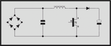
Lars, your core is a RM14, with effective area Ae=2.01cm^2.
If you use 15 primary turns and 320V rectified mains voltage, your peak flux density is:
B=(Vbus/2)*1E8/(4*f*N*Ae)=160*1E8/(4*250000*15*2.01)=500G=50mT
At that operating point (50mT, 250KHz), you must be using a high-frequency material, at least 3F3, in order to reduce core losses, aren't you? (3C90 material won't work well at that freq, for example).
And, according to some references, max. available output power, with that core and operating point is around 750W, not bad for its small size!
Lars Clausen said:
Many use 1 uF caps on the secondary side which is enough to remove most of the HF ripple. However i am using 10000 uF because this way i can maintain some local 'stiffness' after the transformer. Not least to keep control of the rail pumping effects from the Class D modules.
Lars, High value caps at secondary side of High frequency switching supply....is this a good practise...what do you think??
I was once thinking of making an unregulated PSU for an amp too. This has the advantage of simplicity (and intrinsic stability)over a regulated one and of course the advantage of size/weight over a conventional one.
I am not sure but maybe a PFC followed by such an unregulated PSU might also be an attractive solution for audio purposes due to 4 features:
- Could be made working on any mains voltage
- has increased regulation
- can be made CE compliant
- soft start can be made intrinsic to the PFC
Regards
Charles
Hello Charles, and welcome to this thread
Yes i have seen this claim by some vendors of PFC chips, but to me it seems the only thing that is limiting the DC current is the PFC choke, and that will not last more than a few milliseconds. So how does that work?
- soft start can be made intrinsic to the PFC
Yes i have seen this claim by some vendors of PFC chips, but to me it seems the only thing that is limiting the DC current is the PFC choke, and that will not last more than a few milliseconds. So how does that work?
Attachments
Even in the case that PFC doesn't help with soft start, that's only a minor issue as compared with the advantages it offers (pre-regulation, compliance and independency on line voltage).
However, as it can be added as a plug-in before the rest of the supply, I propose to develop the SMPS first and then try to add the PFC if desired.
For particular purposes, a half-bridge with input line filter is more than enough, so few people will want to add the PFC, unless they want to make his home-made amplifier pass CE
Lars Clausen said:If i was making analog amplifiers, i would of course use a smaller cap. But for the reasons already posted, i think it's a good solution.
What do you think?
Oh, The dreaded Bus Pumping caused by Half Bridge ZAP's, thats why you need heftier Bus Capacitors to minimize the Pumping.....
Dear Charles,
PFC is not worth in Pro-amps:
An example :::QSC designed an amp PL6.0 [6000W] which incorporates the PFC , but they have to discontinue that model and they relaunch PL6.0 II , which doesnot have PFC to boost reliability...because that amp made regular visits to their factory....ofcourse for reservicing...
PFC is worth where load demand is constant.....
Since the Power demand in say 2400W Pro-amps ranges from 400 to 2000W instantaneous in peaks during Music transients, therefore PFC doesnot able to cope up with such a rapid change in power demand and thus sometimes fails to ensure the power factor even close to 0.99[]some call it ONE]
But Unregulated Switching Supply is very much reliable in pro-amps due to its non- regulation of secondaries....... and poses less stress
regards,
K a n w a r
Oh, The dreaded Bus Pumping caused by Half Bridge ZAP's, thats why you need heftier Bus Capacitors to minimize the Pumping.....
Yes exactly!
I have to defend Lars in this case. The "dreaded" bus pumping is something inherent to _any_ half-bridge Class-d amplifier, not only ZAP Pulse ;-)
BTW: In my two+ years experience with Class-D, I haven't had any problems with bus pumping. I have gone up to 450W rms with linear supplies and 18000uF and I have NEVER observed an increase in the bus voltage, just the opposite. That's, anyway, the minimum capacitance I would put in any linear power supply. I think we worry too much about this demon
There is a little trick (I think Lars pointed it somewhere): fed each channel with inverted polarities and then re-invert again in the speaker leads. This way the low-frequency content is almost cancelled as it tends to be common to both channels.
In bridge-mode connection, this is inherently done.
About PFC: I agree with Kanwar and wouln't like to implement it, but I think that those arguments won't convince CE authorities anyway. Every equipment above 75W must have PFC if I am not wrong. (If this is not true, please correct me).
However, I have seen docens of PA designs from serious makers out there with powers between 300W and 4KW that don't have PFC. How can this be possible? And, for example, A&T Labs K6 smps doesn't have PFC either and is sold ¿legally?.
Best regards,
Pierre
Pierre said:I have to defend Lars in this case. The "dreaded" bus pumping is something inherent to _any_ half-bridge Class-d amplifier, not only ZAP Pulse ;-)
BTW: In my two+ years experience with Class-D, I haven't had any problems with bus pumping. I have gone up to 450W rms with linear supplies and 18000uF and I have NEVER observed an increase in the bus voltage, just the opposite. That's, anyway, the minimum capacitance I would put in any linear power supply. I think we worry too much about this demon
There is a little trick (I think Lars pointed it somewhere): fed each channel with inverted polarities and then re-invert again in the speaker leads. This way the low-frequency content is almost cancelled as it tends to be common to both channels.
In bridge-mode connection, this is inherently done.
About PFC: I agree with Kanwar and wouln't like to implement it, but I think that those arguments won't convince CE authorities anyway. Every equipment above 75W must have PFC if I am not wrong. (If this is not true, please correct me).
However, I have seen docens of PA designs from serious makers out there with powers between 300W and 4KW that don't have PFC. How can this be possible? And, for example, A&T Labs K6 smps doesn't have PFC either and is sold ¿legally?.
Best regards,
Pierre
Salut Pierre,
I think you contradict your own statement,
You said "you havent encountered Bus Pumping with your modules, but lars is agreeing on the fact that his ZAP's produce Bus pumping, Ok , then where goes the Defending criteria...I think nowhere
About PFC and CE,
There is no Directive stated from the "CE" that Professional amplifiers "Must" incorporate the PFC, but the directive differs somewhat in the view of Home applainces as well as Industrial applainces....But Profesional audio isn't a Home audio nor an Industrial one...
There are many +1KW power level Pro-amps in the market which donot have PFC but yet have "CE" marking on them
So , Pierre correct yourself....
K a n w a r
About bus pumping:
I think I am not contradicting myself. I was not saying that my amplifiers didn't have that problem and that ZAP Pulse may suffer from it either. In fact every half-bridge Class-D shows bus pumping. I was just saying that it is not an important issue provided that you add enough capacitance, in fact the same capacitance I would add to a linear amplifier. IMHO, 10,000 or 20,000uF per rail is quite usual and with that you won't have problems with pumping.
About CE marking and PFC, I don't have any inconvenience in correcting myself, as I was speaking only "by hearings" and I remarked that. In fact I was only throwing the question so others with more experience in that area could clarify it. If PFC is not required, and you are sure about that, we are all happy about that.
Thanks, Kanwar, for the clarifications.
So no problem and we can keep on working on the supply itself.
Lars, have you made any improvement?
However, as it can be added as a plug-in before the rest of the supply, I propose to develop the SMPS first and then try to add the PFC if desired.
Agreed !
I am not sure whether power amps are generally ruled out for needing PFC. I think it all depends on what PSU type is used. If it is a conventional PSU then PFC is not mandatory (and difficult to implement either). But SMPS must have it above a certain power level AFAIK. But I might as well be wrong.
If the PFC is made as a hybrid topology (buck and boost) then it should be possible to implement soft start with it. PFC also has the advantage of causing less noise on the mains.
Keep in mind that one of the major culprits regarding mains pollution are conventional power amps with their beefy conventional PSUs !
How about having a switching amps that excels in this respect ?
Regards
Charles
Lars Clausen said:Yves Smolders: Actually i would prefer it if you would not use my switchmode for your JP modules.
You will end up getting a sound that is lacking dynamic perfomance, and a messy soundstage. I am sure JP will quickly convince you that the problem is not his modules, but the smps. (hmm for obvious reasons).
However using the proposed smps with ZAP modules will give you a highly dynamic, open sound performance with a perfect soundstage. Those are the ones i have been designing the smps for, so i know how it works.
There we go again, UcD bashing. Getting tired of it and why do you need to resort to it every time? Just makes your whole story less believable. It is very nice of you to share all this SMPS info but just keep other amps out of this story.
Best regards
Gertjan
ghemik: I am sorry if my above message can be misunderstood as bashing of your well established friends at hypex. It is not intended. But i really needed to point out the potentially misfortunate outcome, of combining my smps with their amplifiers, especially because the expected problems would normally be associated with power supply problems in general. In fact i can't even be sure their amplifier modules work stable and reliable with the smps that i am building.
So the whole situation could easily be misunderstood, and that is what i want to avoid. I would have made the exact same recommendations for any other amplifier, where i would foresee problems of this kind. But in this case, Yves Smplders asked about using hypex.
You know JP has taken every opportunity to bash my stuff in the past, so let's just say that this way i am trying to minimize the bashing in the future, by keeping our stuff separate. But maybe you hypex fans should ask JP to design a smps, that is fit for his amplifiers, if it is of interest for you?
All the best from
Lars
So the whole situation could easily be misunderstood, and that is what i want to avoid. I would have made the exact same recommendations for any other amplifier, where i would foresee problems of this kind. But in this case, Yves Smplders asked about using hypex.
You know JP has taken every opportunity to bash my stuff in the past, so let's just say that this way i am trying to minimize the bashing in the future, by keeping our stuff separate.
But maybe you hypex fans should ask JP to design a smps, that is fit for his amplifiers, if it is of interest for you? All the best from
Lars
ghemink said:
There we go again, UcD bashing. Getting tired of it and why do you need to resort to it every time? Just makes your whole story less believable. It is very nice of you to share all this SMPS info but just keep other amps out of this story.
Best regards
Gertjan
Hi ghemink
Could you please calm down.
Lars, in his post, was quite clear that the smps was intended for his ZP2.3SE modules. I believe that the smps should also work for the ZP700XE modules. Lars, is that correct?Having said that, you can always try it with your Ucd modules, although Lars believes that it will not work as he intended. Please, let us know what the results are.
krgds
- Status
- This old topic is closed. If you want to reopen this topic, contact a moderator using the "Report Post" button.
- Home
- Amplifiers
- Class D
- Making of Lightforce 1 Class D Powerbriefcase