Hi all,
I thought it is about time i built a class D amp so i could have a listen to the sound and judge for myself if they are any good. I was fed up with everybody presuming they are rubbish or harsh sounding and going around telling everybody just that, even though they havn't actually listened to a class D. So i decided to build one for myself.
My amp is a 75 watt half bridge using no special components working happily on breadboard, with a sampling frequency of around 275Khz. I was shocked with the sound quality when i finally got it to work, i was expecting it to sound like a bad class b PA amp, but it is so crystal clear that i find i can hear new background instruments in music i already know! The bass is like never before, super smooth with loads of power for the sub-sonics Anyway enough of slavering, the reason i'm posting is to ask a few questions about strange happenings that i can't thathom out
1. The whole of the amp runs COLD even after a good hammering, EXCEPT for one part, the output filter inductor, it always runs hot ( approx 40C for 20C ambiant ) even at idle. The inductor is of unknown value since it was pulled out of a computer switch mode supply, however it looks quite substantial, must be more than 500uH at lots of amps. WHY?
2. When operating in open loop mode, there is a very slight background hum from the mains ( due to power supply ripple ) and quite noticable hiss. I presumed before building this type of amp that hiss would definatly not be present, however it is. WHY?- and WERE is it being genarated?
3. I am using spec-matched complimentry fets for the output stage (( N & P type ) IRF9530, IRF520 ) When i run the amp at idle with no heat sink on the fets, the high side ( P ) fet gets slightly warmer than the low side, WHY?
I'm glad i built this amp as i have been blown away by the superiour power handling and absolutely amazing clarity of sound. It truley is the best sounding amp i have ever built, or even listened to, even if it IS still on capacitive bread board
I hope you can help answer my questions.
Mad.P
I thought it is about time i built a class D amp so i could have a listen to the sound and judge for myself if they are any good. I was fed up with everybody presuming they are rubbish or harsh sounding and going around telling everybody just that, even though they havn't actually listened to a class D. So i decided to build one for myself.
My amp is a 75 watt half bridge using no special components working happily on breadboard, with a sampling frequency of around 275Khz. I was shocked with the sound quality when i finally got it to work, i was expecting it to sound like a bad class b PA amp, but it is so crystal clear that i find i can hear new background instruments in music i already know! The bass is like never before, super smooth with loads of power for the sub-sonics
Anyway enough of slavering, the reason i'm posting is to ask a few questions about strange happenings that i can't thathom out 1. The whole of the amp runs COLD even after a good hammering, EXCEPT for one part, the output filter inductor, it always runs hot ( approx 40C for 20C ambiant ) even at idle. The inductor is of unknown value since it was pulled out of a computer switch mode supply, however it looks quite substantial, must be more than 500uH at lots of amps. WHY?
2. When operating in open loop mode, there is a very slight background hum from the mains ( due to power supply ripple ) and quite noticable hiss. I presumed before building this type of amp that hiss would definatly not be present, however it is. WHY?- and WERE is it being genarated?
3. I am using spec-matched complimentry fets for the output stage (( N & P type ) IRF9530, IRF520 ) When i run the amp at idle with no heat sink on the fets, the high side ( P ) fet gets slightly warmer than the low side, WHY?
I'm glad i built this amp as i have been blown away by the superiour power handling and absolutely amazing clarity of sound. It truley is the best sounding amp i have ever built, or even listened to, even if it IS still on capacitive bread board
I hope you can help answer my questions.
Mad.P
Hi,
Sounds to me like you had alot of luck on your side in this endeavour.
Care to post a circuit?
1. Why? Excellent question, you tell me? For one thing it's a mystery core, most likely iron powder, if you were switching faster it would be even hotter, althrough it's probably not operating out of spec at only 40 degrees. If you really want to experience clarity, make an air core inductor for it. Even that will get warm.
2. Why? Because it's not a proper dual layer PCB with SMT. I've found you can breadboard these at low power, you'll never get it perfect that way though. You're switching frequency could be increased as well, and it sounds like you didn't give much attention to the filter values...
3. I almost don't belive you're running it at idle with no heatsinks, Probably the hardest thing you could do to it. Bet that doesn't last too long. P channels are less efficient, what specs did you match?
Regards,
Chris
your breadboard is a horrible device for high frequency applications.
plus it acts like an antannae.
i bet if you re-built your circuit on a PCB, or even just P2P wiring... hum and hiss would go away.
you should post the circuit as well... i never built a class D amp before and if you can build it on a breadboard, i might as build one as well.
cheers,
plus it acts like an antannae.
i bet if you re-built your circuit on a PCB, or even just P2P wiring... hum and hiss would go away.
you should post the circuit as well... i never built a class D amp before and if you can build it on a breadboard, i might as build one as well.
cheers,
The output filter core has a very hard life in a class-D amp. I've tried dust-iron toroidal cores (such as you might use in a buck regulator) and they get very hot. Good quality open-bobbin ferrite inductors work well, but they have a large external field that can cause a lot of problems with magnetic induction on the pcb. There are a few companies now selling precision-gapped ferrite toroids for class-D applications. They are expensive and I've not had the chance to try one yet, but they should work well.
Hmmm,
I can use air cores for the output inductor wound around a plastic former, i use them at work for eddy current probes, the value of them are around 46uH. They are quite hudge though :-(
As for the breadboard causing noise i am well aware of this, the AC hum and any other electrical noise i know about and can cure, it is the hiss ( like pink noise ) that i can't figure out, i was thinking electron vibration and all that. I don't know, maybe it will quieten down when a take it off the bread ( don't worry, the breadboard is only used to prototype on )
My dead time is set at 50n/s, looking at the bridge on a scope this clears the switching by about 25 n/s, considering the rise/ fall time of the bridge is about 10n/s i thought this was a good time to select, not too tight not too sloppy. I read recently that a dead time of 60n/s can cause up to 10% distortion while tightening the time to around 10 n/s lowers this figure to 0.1% Do you think i sould tighen things up or just leave them
Cheers guys, i'll draw up the circuit at weekend and post it along with some photos of the prototype for your amuzement LOL My last amp was a class A, It was nice but ran as hot as a nuclear reactor, i've gone from one extreme to the other!
Mad.P
AC hum is definitely not caused by the board layout but due to the fact the a class-d amp directly switches between the noisy supply rails. It is greatly reduced by NFB though.
But the hiss can be caused by bad layout (transient overshoots reaching the modulator) and use of breadboard. A class-d amp is an EMC hell and therefore great care of layout has to be taken. The PCB is one of the most important electrical components of the amp and it has to be designed and made by YOU. That's a major problem when it comes to the development of class-d amps.
I wish you good luck for your endeavour.
Regards
Charles
Hi,
I just made my own, can't remember it was something like 1 meter of 18awg magnet wire, wound it around a 1" inch socket semi carefully, then while still on the socket I applied a few drops of epoxy on four sides to hold it together. Once dried I took out the socket and gave the whole thing a coating in epoxy, it's still holding together very well It too is the warmest part of my circuit, and is hardly noticeably warm, even at idle.
This overlooks the temperature of the mains transformer though, it's just a 45 VA center tap with 8200uF on each rail or so, plus whatever decoupling on the board.
I was lazy myself and just used an online calculator to come up with the recipe for the air core, winding technique was my own.
I did of course calculate the value of the filter that I wanted the old fashioned way, something like 15uH, and for a cut off of 30Khz at 4ohms.
RFI, EMI, and more resonances than you can shake a stick at, that all sounds like electrical noises to me. The only way to "cure" it, is to do a professional implementation on a worthy PCB.
IT depends on what you do with the input stage/feedback, wires, component orientation etc.
Your worst contributor will be the EMI so you really need to do a good job of it even on a breadboard.
Nice thing here is that since the noise floor is already shot to hell via the EMI, who cares about using an air coil..? It's worth it for the experience, then you'll know what the sound of a core is too, if you're willing to rate the air core as "ideal" sonically. I find it allows you achieve crystal detail and and air even with the reduced noise floor caused by it's increased EMI.
I regret making the mistake of taking my circuit off the bread board and doing it P2P at times. For one thing you've really no excuse not to experiment with it while on their, and burnt components couldnt' be easier to replace. For another surprising factor in my case, I found the circuit missed the capacitance of the board do dampen noise, and having to place the components in accordance with a few traces of my board compromised layout enough as well that the hiss was even more prevalent that before. But you do this for a learning experience not for the ideal amp, maybe it will become a first step to an ideal amp.. I say good luck to everyone there.
BTW right now my amp is dc coupled to my sound card and when the 15' of single ended input wire are unplugged from the card, and left on the amp, only a faint whistle is heard, my speakers are extremely efficient and on anything less it's nearly silent.
It's also 35watts not 75.
Look foward to seeing you're schematic of this, pics would be cool too. I'll be posting some of mine very soon, I have the camera sitting here now.
Regards,
Chris
I just made my own, can't remember it was something like 1 meter of 18awg magnet wire, wound it around a 1" inch socket semi carefully, then while still on the socket I applied a few drops of epoxy on four sides to hold it together. Once dried I took out the socket and gave the whole thing a coating in epoxy, it's still holding together very well
It too is the warmest part of my circuit, and is hardly noticeably warm, even at idle. This overlooks the temperature of the mains transformer though, it's just a 45 VA center tap with 8200uF on each rail or so, plus whatever decoupling on the board.
I was lazy myself and just used an online calculator to come up with the recipe for the air core, winding technique was my own.
I did of course calculate the value of the filter that I wanted the old fashioned way, something like 15uH, and for a cut off of 30Khz at 4ohms.
As for the breadboard causing noise i am well aware of this, the AC hum and any other electrical noise i know about and can cure, it is the hiss ( like pink noise ) that i can't figure out, i was thinking electron vibration and all that. I don't know, maybe it will quieten down when a take it off the bread ( don't worry, the breadboard is only used to prototype on
RFI, EMI, and more resonances than you can shake a stick at, that all sounds like electrical noises to me. The only way to "cure" it, is to do a professional implementation on a worthy PCB.
IT depends on what you do with the input stage/feedback, wires, component orientation etc.
Your worst contributor will be the EMI so you really need to do a good job of it even on a breadboard.
Nice thing here is that since the noise floor is already shot to hell via the EMI, who cares about using an air coil..? It's worth it for the experience, then you'll know what the sound of a core is too, if you're willing to rate the air core as "ideal" sonically. I find it allows you achieve crystal detail and and air even with the reduced noise floor caused by it's increased EMI.
I regret making the mistake of taking my circuit off the bread board and doing it P2P at times. For one thing you've really no excuse not to experiment with it while on their, and burnt components couldnt' be easier to replace. For another surprising factor in my case, I found the circuit missed the capacitance of the board do dampen noise, and having to place the components in accordance with a few traces of my board compromised layout enough as well that the hiss was even more prevalent that before. But you do this for a learning experience not for the ideal amp, maybe it will become a first step to an ideal amp.. I say good luck to everyone there.
BTW right now my amp is dc coupled to my sound card and when the 15' of single ended input wire are unplugged from the card, and left on the amp, only a faint whistle is heard, my speakers are extremely efficient and on anything less it's nearly silent.
It's also 35watts not 75.
Look foward to seeing you're schematic of this, pics would be cool too. I'll be posting some of mine very soon, I have the camera sitting here now.
Regards,
Chris
phase_accurate said:AC hum is definitely not caused by the board layout but due to the fact the a class-d amp directly switches between the noisy supply rails. It is greatly reduced by NFB though.
But the hiss can be caused by bad layout (transient overshoots reaching the modulator) and use of breadboard. A class-d amp is an EMC hell and therefore great care of layout has to be taken. The PCB is one of the most important electrical components of the amp and it has to be designed and made by YOU. That's a major problem when it comes to the development of class-d amps.
I wish you good luck for your endeavour.
Regards
Charles
Right on.
AC hum is also greatly reduced by using enough capacitance in the supply with is... important to do anyway.
"By the way, do you really mean 500uH for the output inductor? They're usually more like 22uH or 33uH."
It's just a guess but it is a very substantial torroid, it may not have been used for output smoothing in its previous life, but even though it is obvious overkill it does a good job and it was the only one i had to hand
You will think i'm crazy when i post the circuit, things arn't exactly as you guys would recommend but i asure you it sounds and works exceptionally well
Anyone know a good schematic capture software package i can use to give you my circuit? Pref freeware, i normally use EasyPc but it wont let me export the schematic as a jpeg for posting, it will only give me .sch files or .dxf files. Ideally i need a dxf/sch file to jpeg conversion program than i don't have to duplicate my work as i do everything in EasyPc both at home and at work for schmatic to pcb layout
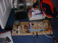
Here is a taster of the amp, you will have to wait till saturday for closer pictures and the schematic as the battries have just died in my camera and i'm off to the pub soon so i'll draw up the circuit for you all tommoz... enjoy and don't kill yourselves laughin
Attachments
Hi,
It looks to me as though you've taken some care in layout, nicely done. That's a great way to do the heatsinking, even of the mosfets heat up they won't melt into the board and short with anything.
My only real concern with your set up is that fork and knife, hope they aren't your test probes.
It looks to me as though you've taken some care in layout, nicely done. That's a great way to do the heatsinking, even of the mosfets heat up they won't melt into the board and short with anything.
My only real concern with your set up is that fork and knife, hope they aren't your test probes.

Hi all,
As promised here are the schematics and pictures of what i've got so far, i know there are improvments to be made, i'm getting round to them. I want to ask everyones advice here, what do you think of leaving the twiddly pot in the design? The blue pot is there to adjust the DC bias of the amp at the speaker output. It seems stable at the mo, but i would rarther add on some kind of self-biasing circuit, just got to think of a good way of doing it so it will start up safley. If you think its o.k however i will be tempted to leave it as it is. Let me know. Also is there any reason why i should not be using as much feedback as i am? It is perfectly stable and well away from any signs of oscillation but what effects can it have on the sound quality? After all that is why i'm using it, to remove any non liniarities in the output filter and to reduce hiss to an undetectable level
Here is the power supply circuit:-
Attachments

- Status
- This old topic is closed. If you want to reopen this topic, contact a moderator using the "Report Post" button.
- Home
- Amplifiers
- Class D
- Breadboard Class D!!