Well I just did an AB comparison between my modded SI and my 6-channel AMP1-B and it almost made me cry. Yes I said cry, because my SI just made $500 worth of parts and over 30 hours worth of effort feel like a waste.
I had just finished making a cardboard mock up of some OB line arrays I plan on building, and just for fun I wanted to see how loud it would play with the SI. As soon as I turned it on my jaw dropped and I asked myself "where the h*ll did that tight defined midbass come from" because it wasn't there a few minutes earlier with the AMP1-B.
I was not at all dissatisfied with the sound of the AMP1-B's before the comparison, but now...............
*sigh* Anyone interested in a 6-channel amp?
Banned
Joined 2002
Banned
Joined 2002
Luke said:interesting,
have these had a lot of good press?
it's just another chip amp.
 WOW!!!
Yeah But a class D one. Tripath are .... I think, probably the first to approach "high end" with class d, they've since been surpassed. For the cost of them though... I'm tempted to try one eventually, people around seem to love them. I bet they spend ten times more modding them than they did on the little amps themselves.
theAnonymous1, let them be tears of joy Welcome to Class D.
But a class D one. Tripath are .... I think, probably the first to approach "high end" with class d, they've since been surpassed. For the cost of them though... I'm tempted to try one eventually, people around seem to love them. I bet they spend ten times more modding them than they did on the little amps themselves.theAnonymous1, let them be tears of joy
Welcome to Class D.Hi,
Wow, I'm sorry I got my threads mixed up, low blood sugar, drunk, actually I wish, there's no excuse for that kind of post, my mind is all over the place today
I see you've done alot of work on this.
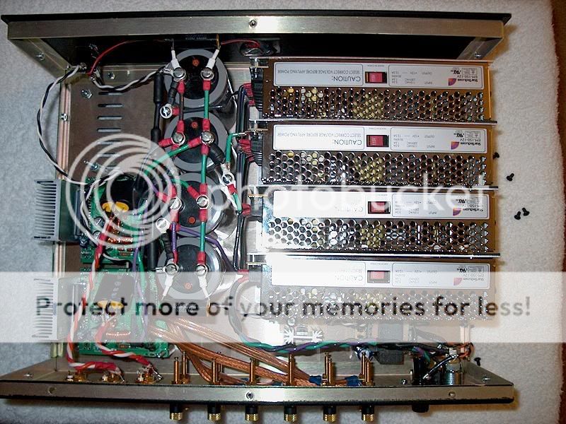
This is the beast with four SMPS in series isn't it?
Do you still have the dummy load connected in series? Maybe that's the problem.
What if you tried something silly like a "speed up" cap in parallel with that series resistor, 1nF maybe, probably less?
It could be the supplies themselves. Maybe you could rig up some batteries or grab another raw DC supply just to test the module itself with, see how it sounds all on its own? You may have further tweaking to do with the local supply/decoupling caps etc, but I think you've been down that road already, right?
Feeding six amps off of four SMPS in series... I'm impressed, but your supplies aren't purpose built either, they simply may not be able to handle the draw that low frequency signals demand (for six amps at a time). Disconnect half the modules and see if it helps? Maybe you could squeeze a little more out of it in the low end if you reversed the phase of three of the amps? Then you at least get supply pumping that works for you, and more efficient use of the power.
Are the high's similar?
Can you post more about what you're actual setup is currently here so we can have a look and figure it out a bit more?
Wow, I'm sorry I got my threads mixed up, low blood sugar, drunk, actually I wish, there's no excuse for that kind of post, my mind is all over the place today
I see you've done alot of work on this.
This is the beast with four SMPS in series isn't it?
Do you still have the dummy load connected in series? Maybe that's the problem.
What if you tried something silly like a "speed up" cap in parallel with that series resistor, 1nF maybe, probably less?
It could be the supplies themselves. Maybe you could rig up some batteries or grab another raw DC supply just to test the module itself with, see how it sounds all on its own? You may have further tweaking to do with the local supply/decoupling caps etc, but I think you've been down that road already, right?
Feeding six amps off of four SMPS in series... I'm impressed, but your supplies aren't purpose built either, they simply may not be able to handle the draw that low frequency signals demand (for six amps at a time). Disconnect half the modules and see if it helps? Maybe you could squeeze a little more out of it in the low end if you reversed the phase of three of the amps? Then you at least get supply pumping that works for you, and more efficient use of the power.
Are the high's similar?
Can you post more about what you're actual setup is currently here so we can have a look and figure it out a bit more?
there is another thread about bass performance of the AMP1B, see for solutions. It should have very good bass performance just like any well designed amp. I dont know what level you want to play? Tried it this weekend with some JM Labs and you can party very well with them.
Hi fellas, long night at work and I see I have lots to reply too.
First let me explain that this is the first project like this I have ever done and I have zero background in electronics, just kinda learning as I go along. I know the very basics like ohms law and never stick a fork in the AC outlet, but not much more.
Welcome indeed, and I'm here to stay for 4sure.
There are 0.2R DIY wire wound resistors in series with +,-, and 0v. There is also a 880 ohm dummy load in parallel from + to -. The 0.2R resistors in series with + and - keep the supply from oscillating at idle, and the one in series with 0v keeps the supply from oscillating when low frequencies are being played. The values and placements for these were all trial and error and had no real "educated" reasons for being placed there. I just kept trying different things until the damn SMPS's stopped clicking.
I unfortunately don't have a trafo or enough batteries to try a different supply.
Sorry if I confused you somewhere classd4sure, its three 2-channel modules for a total of six channels.
Could you elaborate a little more on that please Input signal, output, rails?
The highs seem fine, I couldn't tell any difference when switching to the SI.
The bass is full and plays low and loud, but the midbass seems closed in, kinda cloudy. The SI's midbass is very clear and punchy when compared. Input caps are 3.0uf Dayton polys on the AMP1-B, and 4.7uf on the SI, I doubt that could make that much difference though.
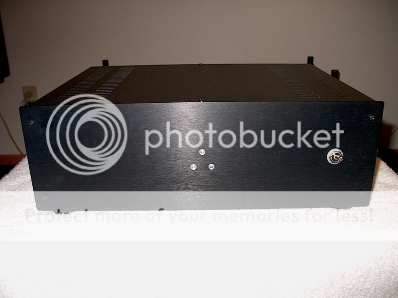
Lemme break out the digi-cam and take some pics.
First let me explain that this is the first project like this I have ever done and I have zero background in electronics, just kinda learning as I go along. I know the very basics like ohms law and never stick a fork in the AC outlet, but not much more.
theAnonymous1, let them be tears of joy Welcome to Class D.
Welcome indeed, and I'm here to stay for 4sure
.Do you still have the dummy load connected in series? Maybe that's the problem
There are 0.2R DIY wire wound resistors in series with +,-, and 0v. There is also a 880 ohm dummy load in parallel from + to -. The 0.2R resistors in series with + and - keep the supply from oscillating at idle, and the one in series with 0v keeps the supply from oscillating when low frequencies are being played. The values and placements for these were all trial and error and had no real "educated" reasons for being placed there. I just kept trying different things until the damn SMPS's stopped clicking.
I unfortunately don't have a trafo or enough batteries to try a different supply.
Feeding six amps off of four SMPS in series...
Sorry if I confused you somewhere classd4sure, its three 2-channel modules for a total of six channels.
Maybe you could squeeze a little more out of it in the low end if you reversed the phase of three of the amps?
Could you elaborate a little more on that please
Input signal, output, rails?The highs seem fine, I couldn't tell any difference when switching to the SI.
The bass is full and plays low and loud, but the midbass seems closed in, kinda cloudy. The SI's midbass is very clear and punchy when compared. Input caps are 3.0uf Dayton polys on the AMP1-B, and 4.7uf on the SI, I doubt that could make that much difference though.
Lemme break out the digi-cam and take some pics.
Luke said:Hi Bert,
I take it youve tried the ucd180/400 and Tripaths?
Which is best of the three?
AMP1B is a very open sounding amp at low to medium levels.
The UCD's just have more authority in the fact that they stay clean till a very high sound level(for me that is).
The AMP1B is very good value and to be honest I think the UCD180's have more than enough power to listen to. The 400's go a notch higher but for me this is not a necessity. But I prefer the AMP1B over f.i. my NAD C162/C272 combo(am going to sell it).
And just for fun, the NAD uses some 100W at low volume while the AMP1B uses something like 8W with a passive preamp.
But because of these huge housings you forget what they consume/use/burn up.
Well, I changed the wire wound resistor on the supply to non-inductive carbon resistors and it seems to have helped. I also disconnected the supply ground from earth ground because it was causing a ground loop when I hooked up my media PC.
On a side note and a bit off topic, I am completely amazed with my cardboard OB arrays. They go insanely loud and I'm only using 2/3 of the drivers and a passive crossovers, finished arrays will have 12 mids and 18 tweeters per side and be Bi-amped and actively crossed. They have more punch than a domestic dispute between Whitney Houston and Bobby Brown .
.
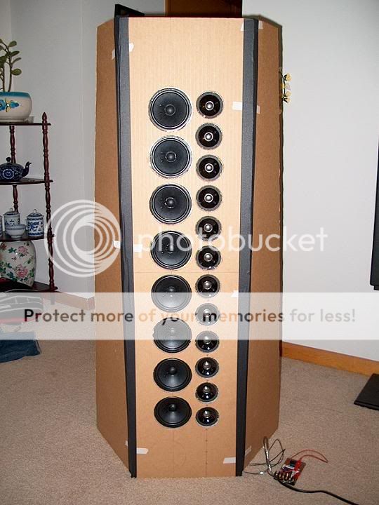
On a side note and a bit off topic, I am completely amazed with my cardboard OB arrays. They go insanely loud and I'm only using 2/3 of the drivers and a passive crossovers, finished arrays will have 12 mids and 18 tweeters per side and be Bi-amped and actively crossed. They have more punch than a domestic dispute between Whitney Houston and Bobby Brown
.
OK, I did some power tests today. I need you smart fellas to tell me if it all adds up.
For dummy loads I used 4 and 8 ohm 10w resistors, I figured with the power range I would be measuring they would survive OK.
Now, I don't have a scope so I had to make a poor mans "clipping indicator". I took a 4 ohm tweeter and put a 1uf cap and 30 ohm resistor in series with it, this let me hear when the amp started to distort but didn't effect the test because I used a 99hz sine. 99hz is as high as my test disk goes and its within my meters 50-400hz range.
When I ran the test I turned the volume up until I heard distortion through the tweeter then backed it down until it was gone.
Results:
8 ohms: 14.5v 3.6a = 52.2w
4 ohms: 14.8v 1.8a = 26.64w
I mentioned before that this stuff is kinda new to me, so I assume that theoretically the voltage should be the same for both loads, but the current should double into 4 ohms?
Do these numbers seem accurate for 28v rails?
Thanks in advance guys.
theAnonymous1 said:8 ohms: 14.5v 3.6a = 52.2w
4 ohms: 14.8v 1.8a = 26.64w
Do these numbers seem accurate for 28v rails?
For starters, you have the 8ohm and 4ohm cases switched
So from what I gather, your setup had the 30ohm resistor, cap, and tweeter in parallel with the dummy load connected to the amp's output. Unless your supply voltage was seriously dropping for whatever reason I don't see how you could only measure 14.8Vrms at clipping with 28V rails.
Assuming the Tripath chip output can come within about a volt of the actual rail, ±28VDC rails would give you a 27V peak (which is 19Vrms for a sinusoid).
For a 4ohm load that would be (19^2)/4=91W/ch.
For an 8ohm load that would be (19^2)/8=46W/ch.
Can those switching supplies in series handle up to 5A of current draw? I suspect that the supplies may be the reason for the poor sound you're hearing. Do you have a linear supply from another amp that you could test the modules out with?
For a small investment you could get one of these and a couple high current bridge rectifiers:
http://www.partsexpress.com/pe/showdetl.cfm?&DID=7&Partnumber=122-655
and just plop it in place of your SMPSes - assuming your supply caps are rated for at least 40VDC since that transformer would give you around 35VDC rails.
theAnonymous1 said:Could you elaborate a little more on that please
Since he thought you were using 6 modules, he mentioned reversing the phase (reverse the connections of the input signal and also the output signal so that all the signals effectively remain in phase) of three of them so that you could effectively reduce possible power supply pumping issues. You could do this with one channel of each amp. In fact I remember reading that Tripath even suggested this if you have supply pumping issues. I'll go look through the application notes to see if I can find that for ya.
Ah, found it! Application Note 9 explains it quite well and even has a connections diagram.
http://www.tripath.com/downloads/an9.pdf
- Status
- This old topic is closed. If you want to reopen this topic, contact a moderator using the "Report Post" button.
- Home
- Amplifiers
- Class D
- SI beats my AMP1-B's