Re: Grounding issue?
Hi,
Just to add to the above,
It looks like you're XLR shields are grounded between the caps, they should directly go to the the star point, certainly not between the caps.
Also did you enable the modules to oscillate, or just test DC output with them disabled. I wouldn't be shocked to find the two readings differ a large amount, it's what you read with them oscillating that matters.
sx881663 said:Please remove the plastic jackets from the terminals and solder the wires to them if you don't have a crimper. Put shrink tubing over them for protection afterward. The ground wire from your common point is probably open or high resistance. It should also be heavy gauge and connected directly to the ground between the 2 caps. This wire has to handle the full current and needs to be away from the star point so as to not contaminate it.
Roger
Hi,
Just to add to the above,
It looks like you're XLR shields are grounded between the caps, they should directly go to the the star point, certainly not between the caps.
Also did you enable the modules to oscillate, or just test DC output with them disabled. I wouldn't be shocked to find the two readings differ a large amount, it's what you read with them oscillating that matters.
A question of clarity!
I reread my post and realized it isn’t very clear as to what I was referring to. The small black twisted pair wire from the modules ground going to the star point is the one I was referring to that should be short, direct, larger and connected between the caps. This wire is important as it carries considerable signal current. While you are into it twist the red/black wire pairs from the bridge rectifiers to the caps. This wire pair handles large ripple currents and will be a potential noise source otherwise.
Roger
Grounding
Chris,
Yes that would be right if you could connect a wire from the UcD ground connection point to the star point. It is my understanding that this connection on the module is the actual reference point. Unfortunately connecting 2 wires to those fast-on terminals is not a good idea as the smaller wire is prone to breakage. The next best point would be another connection to the cap center point. If the wire used to connect this point to the module is very heavy gauge and short you don’t give up much. With the dual bridges connecting directly to the caps there should only be output signal return current in this wire, no line related ripple. This means there will be a small AC signal related drop between the star point and the actual reference. This shouldn't be problematic. Any switching residual getting into this point should be small enough and high enough in frequency to be ignored.
We may be picking nits here and need advice from Bruno whom I am sure has measured it 10 ways from Sunday. The really important thing is to not make any ground connections to the – speaker lead or introduce supply ripple currents into the reference ground. Any noise voltage here gets multiplied by the amps gain.
Ever notice how nothing is ever simple when you get into it?
Roger
Hi,
I'm a bit confused by your reply so..... hang on.
My understanding of Star grounding is "1 point". But that's a little oversimplified. You can have multiple grounds connecting to each other at various places, as long as they all connect at one point eventually.
This is what we have on the UCD module. The output ground (speaker's) connection is directly connected to the ground terminal, there's zero ohms between them, we've been given that second wire.
The module senses the speakers ground from there, odds are it makes it less likely a user will screw it up doing their own layout if they take away your choice of where you're going to sense the load's ground from, and it saves us drilling for core samples too I'm sure")
So yeah it's a reference but it's just a ground reference, we want to connect it to the cleanest spot possible dont' we, yet not create a ground loop.... bring it to that one point.
I think he did it right. I think you've got a great eye for detail though, and yes, he made a bad decision on the wire gauge, it should be the same gauge as the + output.
This has come up a few times now from time to time. If I look at the connection diagram on the data sheet for the module it proves me wrong in an instant.... reading Doug Self's book and everything else I can find on it proves otherwise. I'll not the data sheet diagram doesnt' portray or even mention a proper star grounding technique...
I think if it works between the caps that's great... I'll try mine on the star point and if it works I'll leave it there, if not, it's to the caps they go!
I'm a bit confused by your reply so..... hang on.
My understanding of Star grounding is "1 point". But that's a little oversimplified. You can have multiple grounds connecting to each other at various places, as long as they all connect at one point eventually.
This is what we have on the UCD module. The output ground (speaker's) connection is directly connected to the ground terminal, there's zero ohms between them, we've been given that second wire.
The module senses the speakers ground from there, odds are it makes it less likely a user will screw it up doing their own layout if they take away your choice of where you're going to sense the load's ground from, and it saves us drilling for core samples too I'm sure
So yeah it's a reference but it's just a ground reference, we want to connect it to the cleanest spot possible dont' we, yet not create a ground loop.... bring it to that one point.
I think he did it right. I think you've got a great eye for detail though, and yes, he made a bad decision on the wire gauge, it should be the same gauge as the + output.
This has come up a few times now from time to time. If I look at the connection diagram on the data sheet for the module it proves me wrong in an instant.... reading Doug Self's book and everything else I can find on it proves otherwise. I'll not the data sheet diagram doesnt' portray or even mention a proper star grounding technique...
I think if it works between the caps that's great... I'll try mine on the star point and if it works I'll leave it there, if not, it's to the caps they go!
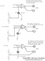
A final point
If we agree that the point on the module where all the grounds come together is the true reference then this is the true star ground point and all other points are referenced back to it. A true reference point connects to all the other points with a single wire so there is no current flow only the transfer of the absolute voltage. Obviously we can’t have this in this situation as we have many and various currents flowing into and out of this reference point. In order to transfer the absolute value of voltage from this reference point to another point we are calling the star ground it is very necessary that this particular connection not carry any current other wise the I/R drops will mean the star point is not at the true reference potential. To do this requires the extra connection to the cap tie point to carry the heavy output signal current. I will want to experiment and make this particular connection directly to the – speaker terminal using the connection from there to the module as only a low current reference ground tie point.
This gets hard to visualize so I will do a drawing.
I had to develop a good understanding of grounds when I designed a very high resolution scale system. LSD was 10nV! I did make it work but it took some effort.
Roger
How can I post with reasonable resolution? I keep getting rejected for too large a file.
Attachments
Hmmmmm,
First of all, I feel I know you well enough to say, curse you for making me spend time in MS Paint!
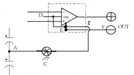
That's not really at all how I view the module. So I've edited your drawing to better reflect my vision of it, and how I would therefore implement it.
I also think this better depicts possibly why Hypex hasn't spelled out to use a star scheme. It's already there where it matters most.
In fact the true reference you're after is not simply earth potential, it's that which the source see's, anything less is a mean ground loop.
There's only one ground comming off the module, the other two are more like ground inputs, but they all interconnect within, forming a star if you will, which you then branch off to the main star with a single wire, and the node between PSU caps connects there as well, with the heavy gauge, short lead.
What do you think?
Don't know about the file size issue, black and white is usually alright. Saving them in .PNG makes them a bit smaller and I find the quality is better, or you could have split it up into three, or zipped it.
Regards,
Chris
First of all, I feel I know you well enough to say, curse you for making me spend time in MS Paint!
That's not really at all how I view the module. So I've edited your drawing to better reflect my vision of it, and how I would therefore implement it.
I also think this better depicts possibly why Hypex hasn't spelled out to use a star scheme. It's already there where it matters most.
In fact the true reference you're after is not simply earth potential, it's that which the source see's, anything less is a mean ground loop.
There's only one ground comming off the module, the other two are more like ground inputs, but they all interconnect within, forming a star if you will, which you then branch off to the main star with a single wire, and the node between PSU caps connects there as well, with the heavy gauge, short lead.
What do you think?
Don't know about the file size issue, black and white is usually alright. Saving them in .PNG makes them a bit smaller and I find the quality is better, or you could have split it up into three, or zipped it.
Regards,
Chris
Attachments
Very interestings thoughts from you guys though you got me a little lost techically speaking. I'm sorry about the quality of the photos above, so I drew this little thing to make it easier (signal connection is not represented):
In fact, i've used two small cable to connect supply ground from the UCD to the ground point (which is the srcew where the trafo is well .... screwed!). I should replace these very soon with proper speaker cable.
When I look at the UCD manual it's true that this wire goes from the module to the caps ground and then to the chassis ground, I'll try that, although classD4sure doesn't agree.
Apart from that, I checked all cables continuity and it's good, the blue LED on the module shows its soft light, so I guess I'm not so far from hearing sound coming ou of it
Cheers
An externally hosted image should be here but it was not working when we last tested it.
In fact, i've used two small cable to connect supply ground from the UCD to the ground point (which is the srcew where the trafo is well .... screwed!). I should replace these very soon with proper speaker cable.
When I look at the UCD manual it's true that this wire goes from the module to the caps ground and then to the chassis ground, I'll try that, although classD4sure doesn't agree.
Apart from that, I checked all cables continuity and it's good, the blue LED on the module shows its soft light, so I guess I'm not so far from hearing sound coming ou of it
Cheers
classd4sure said:Hmmmmm,
First of all, I feel I know you well enough to say, curse you for making me spend time in MS Paint!
That's not really at all how I view the module. So I've edited your drawing to better reflect my vision of it, and how I would therefore implement it.
I also think this better depicts possibly why Hypex hasn't spelled out to use a star scheme. It's already there where it matters most.
In fact the true reference you're after is not simply earth potential, it's that which the source see's, anything less is a mean ground loop.
There's only one ground comming off the module, the other two are more like ground inputs, but they all interconnect within, forming a star if you will, which you then branch off to the main star with a single wire, and the node between PSU caps connects there as well, with the heavy gauge, short lead.
What do you think?
Don't know about the file size issue, black and white is usually alright. Saving them in .PNG makes them a bit smaller and I find the quality is better, or you could have split it up into three, or zipped it.
Regards,
Chris
As to using paint, I refuse! Hate it! Try downloading a free trial version of SmartDraw. I don’t know if it turns off after the trial period or just adds the trial message at the bottom.
It is really nice the way you can output in just about any format. Too bad it is just too expensive for me.
http://www.smartdraw.com/product/ste/index.htm
Your drawing is essentially the same as the one I did only showing a further connection that I didn't. All the points I made about current flow still are valid! I/R drops along the path will degrade the reference to the point that output no longer is a true function of input if it is referenced to the external star point. The only place it would be correct is referenced to the point D on your drawing. Of course if the input is fully differential there should be no problem.
Like I said we may be picking nits here and need some input from Bruno. Wonder if he is back from his trip?
Roger
sx881663 said:we may be picking nits here...
Speaking of that, I see the upper right diode in the lower bridge of kepa1's picture is reversed
Carry on!
Good eye!BWRX said:
Speaking of that, I see the upper right diode in the lower bridge of kepa1's picture is reversed
Carry on!
Of course it isn't in the actual circuit.
Roger
May I suggest a grounding technique which I have used for my UCD400 modules which gives excellent results.
Back in the 80s I built some linear kit amps which suffered from intractable hum problems and also instability when driving QUAD ELS;the instructions with these amps showed a direct connection between the smoothing caps centre tap to chassis,hence to mains ground.
Shortly after building these modules I read an article by Les Sage of SAGE AUDIO UK about grounding techniques which stated that the above type of connection was to be avoided due to the likelyhood of eddy currents flowing through the chassis inducing instability and hum problems,exactly what I was experiencing!
His suggestion was to reference the circuitry to mains ground as far away from the power supply as possible:I.E. direct connection of smoothing caps centre tap to modules and then chassis to input signal ground via 100 ohm ground lift resistors.
Adopting this type of grounding scheme resulted in complete absence of hum and instability.
My UCD modules are suberbly quiet,absolutely no fundamental or harmonic hum detectable even with an ear placed right against speaker drive units.
Hope this suggestion may be of use.
Bob Lewis
I alwys earth my system at the caps star/centerpoint where all the 0V amp. leads and tranformer 0V leads come together. That's my only earthpoint. I want channel separation to be 90db at least at 15kc at low/full power. I always use single rectifiers for my amps. 1 for each amp. never had any humm.
BOB LEWIS said:May I suggest a grounding technique which I have used for my UCD400 modules which gives excellent results.
Back in the 80s I built some linear kit amps which suffered from intractable hum problems and also instability when driving QUAD ELS;the instructions with these amps showed a direct connection between the smoothing caps centre tap to chassis,hence to mains ground.
Shortly after building these modules I read an article by Les Sage of SAGE AUDIO UK about grounding techniques which stated that the above type of connection was to be avoided due to the likelyhood of eddy currents flowing through the chassis inducing instability and hum problems,exactly what I was experiencing!
His suggestion was to reference the circuitry to mains ground as far away from the power supply as possible:I.E. direct connection of smoothing caps centre tap to modules and then chassis to input signal ground via 100 ohm ground lift resistors.
Adopting this type of grounding scheme resulted in complete absence of hum and instability.
My UCD modules are suberbly quiet,absolutely no fundamental or harmonic hum detectable even with an ear placed right against speaker drive units.
Hope this suggestion may be of use.
Bob Lewis
Bob,
Eddy currents in the chassis? Yes this is quite standard any time you have a transformer involved. There will be stray magnetic fields and these will induce currents into the chassis. Since the chassis is a solid piece of metal it looks like a short to the fields therefore you have current flow i.e. eddy currents. This acts like shielding as this stops the fields from going any further. The problem here is not voltage but current. A wire run along the chassis where these induced currents are circulating will act like a partial transformer winding and will pick up some of the residual. Twisted pairs or shielded wire solves most of this problem. The other thing is if the chassis is not grounded with a single point there is the chance of current flow through it. Current likes to flow the path of least resistance so this will probably be a straight line between the connections. Any parts or wiring in this area have a possibility of picking some of this up.
Your method of grounding the circuit is part of a solution to the “pin one problem” and is well documented. Do a Google search for further information. (Use the quotes or you will get hundreds of useless links.) I didn’t discus any of this as it is a whole other subject and a complex one at that. Books have been written on the subject of grounding, in fact several. (Once again do a search.) There also are a ton of app notes available, some of the best available are from National Semi. These particular notes go into some of the things previously discussed in great length and are worth looking at if not actually studying. They go into great detail describing how a few microvolts of voltage drop in a ground connection can upset a circuit so much it is no longer useful! Jensen Transformers also has a series of white papers on the subject that have a lot of good information. Print a copy of some of them and take them into the throne room for your personal edification.
In this forum we can only respond to specific questions or problems other wise we would be writing books here.
Roger
Everything must come to an end, and yesterday I took a big step and connected a crappy speaker to the output of the UCD 
And guess what, all DC output suddenly vanished. In fact when driving a speaker the UCD delivers a tiny 2mV DC On the contrary, when no load is connected the UCD can output quite high DC and this was rather scary.
After that it was time to connect the Beyma woofer... The results were rather pleasant with sweet bass and good control.
Now, I will let my amp break in and compare it with my Linn LK280 to see what happens.
Anyway, thanx for all the good advice and information from DIYaudio members - what a great forum !
And guess what, all DC output suddenly vanished. In fact when driving a speaker the UCD delivers a tiny 2mV DC
On the contrary, when no load is connected the UCD can output quite high DC and this was rather scary.After that it was time to connect the Beyma woofer... The results were rather pleasant with sweet bass and good control.
Now, I will let my amp break in and compare it with my Linn LK280 to see what happens.
Anyway, thanx for all the good advice and information from DIYaudio members - what a great forum !
I need a little help please. I breadboarded a stereo (dual) UCD180 with a single power supply. All okay. When I added the second power supply for a dual mono power supply setup, the second channel did not perform the same as the first.
The secondary outputs on the Avel Y236802 is giving me 34 and 30 VAC relative to the center tap. After the rectifier I am getting about -39 and +46 VDC into the filter capacitor bank. The UCD180 module does not like it any more than I do and it switched off and on about every 2 seconds.
Am I stuck getting a new transformer or changing the windings on this torroidal transformer?
Any tips would be appreciated. From reading the posts on Class-D I see that transformer power is crucial for really good sound and I was hoping to go dual mono.
Does anyone have tips on how to salvage this situation.
Thank you.
Adam
adam12 said:I need a little help please. I breadboarded a stereo (dual) UCD180 with a single power supply. All okay. When I added the second power supply for a dual mono power supply setup, the second channel did not perform the same as the first.
The secondary outputs on the Avel Y236802 is giving me 34 and 30 VAC relative to the center tap. After the rectifier I am getting about -39 and +46 VDC into the filter capacitor bank. The UCD180 module does not like it any more than I do and it switched off and on about every 2 seconds.
Am I stuck getting a new transformer or changing the windings on this torroidal transformer?
Any tips would be appreciated. From reading the posts on Class-D I see that transformer power is crucial for really good sound and I was hoping to go dual mono.
Does anyone have tips on how to salvage this situation.
Thank you.
Adam
It's hard to tell without knowing how you wired it, but I'd say start by making sure you have all the phases of the secondaries in proper order. If you have a static shield with it make sure it's earthed. Is your center tap earthed? Double and triple check your rectifier connections as the next step.
Can give more help if you gave us a schematic of how you wired it or a picture maybe.
Oh, and for your own good, keep your modules disconnected until you get this sorted out.
classd4sure,
Thanks for the advice. I broke it all down and tested each transformer and rectifier stage separately. I was second guessing the ratio of the windings but my issue was sharing a couple connections on the secondaries in parallel. Dumb.
Boy it sure sounds different from the 300B. I am not sure if there is a break in period but it will take a bit of getting used to.
Thanks for your help.
Adam
- Status
- This old topic is closed. If you want to reopen this topic, contact a moderator using the "Report Post" button.
- Home
- Amplifiers
- Class D
- Basic questions for the power supply