I recently designed and built a custom four channel Class-T integrated amplifier based on a pair of TA0102A drivers from Tripath for a Senior Design Project. The system incorporated a four channel preamp with bass, midrange, treble, volume, and balance for each pair of channels. Each pair of channels are bridgeable from a switch on the front panel and another switch allows for user selectable mute. Overcurrent and overvoltage protection. Each channel has 190WRMS into 4ohms and about 90WRMS into 8ohms. The system can bridge to over 300WRMS per channel. The power supply is scalable an can be changed to accomodate higher voltage rails and a different series of drivers. The power supply starts with an offline active power factor correction circuit which switches an output voltage up to 400VDC while maintaining a AC line power factor of no less than 0.99 under all conditions. The 400VDC bus is fed into a Zero-Voltage Switching power supply with average current-mode control. The ZVS converter is a resonant power supply topology which is very similar to the full-bridge except for without the disadvantages. The ZVS switches the transistors when the voltage across them is zero volts and thus eliminating any switching noise. The only disadvantage to this converter is obtaining zero voltage switching over a large load range. The bottom line is: The system weighs less than 8 pounds and fits inside a chassis which is less than 1/3 of a cubic ft. I am thinking about starting a web page highlighting the beginning to end build of one of these units. There are custom double-sided circuit boards with silkscreen and solder mask, custom magnetics design, thermal design, and switching design. It may be able to teach some good stuff to some who have never designed in this arena before. I am just trying to see what the interest in this project would be and if there is an interest I have two units that can be built. There were six total (4 were sold). Let me know if there is any interest to follow this project and I will post some project pages.
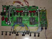
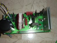
Here is a picture of a prototype system outside of the case and with informal wiring.
BeanZ
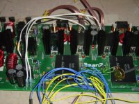
Here is a picture of a prototype system outside of the case and with informal wiring.
BeanZ
I have received a lot of interest in this project over the last few months and a bunch more just recently. I will soon make available some of the design details. If one attempts to work with the switching power supply as will be described in the next few weeks, keep in mind that there exists potentiall Lethal voltages in excess of 400VDC with many joules of energy behind it. Also keep in mind that the entire PFC circuit is entirely a mains circuit which means that the circuit is not isolated and is referenced to the neutral of the AC line...an isolated channel o-scope should be used or run two channels differentially. If an isolated channel scope is not used, then the circuit will be referenced to earth an will explode. The amplifier is based on the TA0102A driver modules which are now discontinued and difficult to get. However, the pin out is the same of the TA0104 and TA0105 modules and with minimal changes to components selection the same board can be used. I will present the design as a gradual design and build of such and amplifier and power supply. Keep in touch for the upcoming saga!!!!
BeanZ
BeanZ
That last post was submitted over a year ago but finally I am going to sit down and share this design with our community. Again this design is an integrated four channel Class-T based audio amplifier. The features include:
--1000W Active Power Factor Correction Circuit
--Zero-Voltage Switching Power Supply
--Four Channel 190WRMS x 4 @ 4ohms
--Simple pre-amplifier with bass, treble, midrange, balance,
volume control for each stereo pair.
--Over voltage, short-circuit protection
The project includes printed circuit boards and a chassis. Stay tuned for pictures and details of the contruction.
Here is the fundamentals for anyone who want to do any pre-research......
PFC is based on the TI UC3854 Power Factor Controller
ZVS is based on the TI UC3875 Phase Shift Resonant Controller
Amplifiers based on the Tripath TA0102A modules.
Feel free to send emails directly to me or post any questions and I will try my best to answer them. I have some extra boards and parts that will be available if anyone is interested.
BeanZ
Banned
Joined 2002
BeanZ,
Do you have the pictures of this project?
All,
I am very interested in the tripath eval boards. I have searched here and elswhere to find DIY amps using these boards and found very little. I read the review of the Veritas P400 amp a couple of years ago which commented that it was a fine amp. It seem that it should be possible to build a very high performace amp using tripath boards for a failrly small amount of cash ! I am sure there must be a reason why this isnt being done?
Any pointers to amps built with these boards or info about them and why they dont seem very popular would be appreciated.
Thanks.
hi
i have gone over the entire tripath cd information kit sent to me by a friend
at my end i have made mosfets , msofets and more mosfets
i would like pricing info
as
as of now to me irf s 150 ets r the best , powerful , high spls clean and have very high degree of critical application properties + are rock soilid
i have had lots of experince in pro audio and serious sound reinforcement
one of the products that have 9i have always admired is meyer s
and meyers uses IRF 150 s , if you hear a meyer (thats an IRF playing)
though i dont want to undermine tripaths research and products or their quality , i really need to compare the price ing
and a justifiable price reduction thru saving on the power supply in tripath applications compaired to the price of the modules pcb s ets
another thing i would like to point out is to the availability of the tripath modules should a company use them - will a service engineer have access to spare modules (world - wide)
and how many service engineer will be familar with this stuff - unless aggressive marketing is done and tech info is published in electronics magazines ets
as for the IRF s they are 65 cents each here in india from Harris tech
suranjan
transducer design engineer
The Class-T Preamplifier
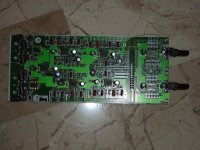
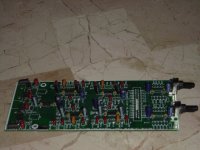
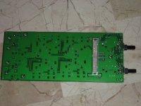
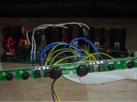
Finally I have gotten around to taking pictures. There have been a lot of you sending me emails with a lot of interest and I will do my best to get back to everyone. If you have questions feel free to email and I will answer them the best I can. The first set of pictures are of the simple preamplifier. It provides simple buffering, gain, and a 3 band EQ based on op-amp gyrators. Also on this board are the circuits for gain and balance. Also, there is a pair of relays that provide alternate signal routing and turns the four channels into a pair of higher power bridged channels. The bridging relay simply takes one of the input signals and applies it to two channels through buffers where one is inverting and one is non-inverting. The question some of you may have at this point is where are all the user controls? The appropriate analog signals run through a sort of ribbon cable to a slim circuit board which holds most of the controls. It will be seen a little later. So here are a couple of shots of the Class-T 4 Channel Preamplifier.
Once again the pictures are too big. Most are around 145kB. I will compress them a little in a couple days and post them here. Coming up next: The PFC front end to the power supply.
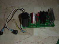
Active Powe Factor Correction
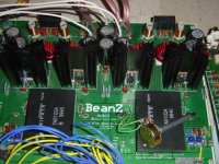
The Active Power Factor Correction PreRegulator circuit provides a 400VDC bus voltage to be presented to the input to the proceding converter stage. The fundamental topology of this circuit is a continuous boost converter where the input in a rectified AC haversine and the output is a DC voltage with ripple. If you are not familiar with the boost topology it consists of a transistor switch, a diode, an inductor, and a capacitor. This particular PFC is designed to power limit at 1000W and does so. All of the magnetics on this and the rest of the circuits are custom designed and hand wound personally. The boost inductor here has a core material of High Flux MPP (moly permalloy powder) and solid 13AWG wire. The exact value of inductance is not as important as the current rating, the losses, and the amount of energy storage (ultimately proportional to inductance though). It is important that the components used be correctly rated including the diode bridge which will be exposed to 400V plus. This particular one is rated for 600V. Enought with the text....here is some pictures. I can answer any questions anyone may have.
The Active Power Factor Correction PreRegulator circuit provides a 400VDC bus voltage to be presented to the input to the proceding converter stage. The fundamental topology of this circuit is a continuous boost converter where the input in a rectified AC haversine and the output is a DC voltage with ripple. If you are not familiar with the boost topology it consists of a transistor switch, a diode, an inductor, and a capacitor. This particular PFC is designed to power limit at 1000W and does so. All of the magnetics on this and the rest of the circuits are custom designed and hand wound personally. The boost inductor here has a core material of High Flux MPP (moly permalloy powder) and solid 13AWG wire. The exact value of inductance is not as important as the current rating, the losses, and the amount of energy storage (ultimately proportional to inductance though). It is important that the components used be correctly rated including the diode bridge which will be exposed to 400V plus. This particular one is rated for 600V. Enought with the text....here is some pictures. I can answer any questions anyone may have.
Attachments
- Status
- This old topic is closed. If you want to reopen this topic, contact a moderator using the "Report Post" button.
- Home
- Amplifiers
- Class D
- Class-T Integrated Amp?