That picture isnt' really enough to tell us anything. I'm wondering if your supply is simply inadequate. I notice no degradation at 100mA limit.el`Ol said:This is how voltage stabilization plus current limit typically works.
Where did you measure? At the output or at the power supply?
I don`t know how my power supply exactly works. It has an IC for that, like almost any power supply.
From the sonic impression I also don`t believe it is compression, because it doesn`t sound less linear and normally any compression worsenes the timing instead of improving it. I believe it could change the noisefloor somehow. But then you have bad cards, at least with equipment below 10000$, because the human ear is the most sensitive measurement device for that.
When I had mine hooked up initially for basic "did I fry it while playing", testing, it had a typical bench supply capable of a little over 3A continuous (though it never came close to that), 13.2V, followed by an add-on LM317 (basic reference LM317 current limiter circuit). The primary observation was that when current was limited around 100mA, it couldn't play as loud before distorting. It was measured after the bench supply, between the inline limiter and the SI board.
While some may go overboard with power, crazy things like 1 farad caps and hundred amp SLAs, powering these is really quite simple-
Digital amps don't need really clean power. "Need" as-in, there shouldn't be a benefit. That's not to suggest any-old unregulated wall-wart is a good idea, only that you dont' need some super-Jung-regulator circuit, any typical LM78xx with a 2A transformer in front of it and 10K mfd post-regulator should be quite sufficient. Many of the consumer Class-D even use a rather basic SMPS. What is useful is a large, low impedance surge curent capability no matter how small or large the front-end of the power source is.
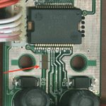
There is another limitation though, the circuit board itself. For optimal power delivery it would be best to scrape off the coating on the back of the board and put low impedance conneection between those two (0.1 mfd ceramics?) where the via goes through to the other side. That's about as short a path as you'll reasonably get unless you feel daring enough to pull up the power pins and solder directly to them.
"Optimal" though, may be overrated. Main point is, 1 farad sitting across a power cord, jack, switch and tiny circuit board traces is generally not as effective as lesser capacitance more local to the chip.
If you look at the rail trace going to/fro the electrolytic on the PCB, there is another opportunity to add a [ceramic, relatively large value) chip cap(s)- with a fine soldering iron it can be bridged between that trace and the GND pad next to the mounting hole- but then it may be less compatible if you use those holes to mount it. Might be easier to understand with a picture:
While some may go overboard with power, crazy things like 1 farad caps and hundred amp SLAs, powering these is really quite simple-
Digital amps don't need really clean power. "Need" as-in, there shouldn't be a benefit. That's not to suggest any-old unregulated wall-wart is a good idea, only that you dont' need some super-Jung-regulator circuit, any typical LM78xx with a 2A transformer in front of it and 10K mfd post-regulator should be quite sufficient. Many of the consumer Class-D even use a rather basic SMPS. What is useful is a large, low impedance surge curent capability no matter how small or large the front-end of the power source is.
There is another limitation though, the circuit board itself. For optimal power delivery it would be best to scrape off the coating on the back of the board and put low impedance conneection between those two (0.1 mfd ceramics?) where the via goes through to the other side. That's about as short a path as you'll reasonably get unless you feel daring enough to pull up the power pins and solder directly to them.
"Optimal" though, may be overrated. Main point is, 1 farad sitting across a power cord, jack, switch and tiny circuit board traces is generally not as effective as lesser capacitance more local to the chip.
If you look at the rail trace going to/fro the electrolytic on the PCB, there is another opportunity to add a [ceramic, relatively large value) chip cap(s)- with a fine soldering iron it can be bridged between that trace and the GND pad next to the mounting hole- but then it may be less compatible if you use those holes to mount it. Might be easier to understand with a picture:
Attachments
! said:When I had mine hooked up initially for basic "did I fry it while playing", testing, it had a typical bench supply capable of a little over 3A continuous (though it never came close to that), 13.2V, followed by an add-on LM317 (basic reference LM317 current limiter circuit). The primary observation was that when current was limited around 100mA, it couldn't play as loud before distorting. It was measured after the bench supply, between the inline limiter and the SI board.
While some may go overboard with power, crazy things like 1 farad caps and hundred amp SLAs, powering these is really quite simple-
Digital amps don't need really clean power. "Need" as-in, there shouldn't be a benefit. That's not to suggest any-old unregulated wall-wart is a good idea, only that you dont' need some super-Jung-regulator circuit, any typical LM78xx with a 2A transformer in front of it and 10K mfd post-regulator should be quite sufficient. Many of the consumer Class-D even use a rather basic SMPS. What is useful is a large, low impedance surge curent capability no matter how small or large the front-end of the power source is.
There is another limitation though, the circuit board itself. For optimal power delivery it would be best to scrape off the coating on the back of the board and put low impedance conneection between those two (0.1 mfd ceramics?) where the via goes through to the other side. That's about as short a path as you'll reasonably get unless you feel daring enough to pull up the power pins and solder directly to them.
"Optimal" though, may be overrated. Main point is, 1 farad sitting across a power cord, jack, switch and tiny circuit board traces is generally not as effective as lesser capacitance more local to the chip.
If you look at the rail trace going to/fro the electrolytic on the PCB, there is another opportunity to add a chip cap- with a fine soldering iron it can be bridged between that trace and the GND pad next to the mounting hole- but then it may be less compatible if you use those holes to mount it. Might be easier to understand with a picture:
On the power supply issues, you are right about super regulation not being much benefit as this usually only relates to very low freq performance which we can’t hear directly. However most super regulators also are very low noise and have low source impedance. This will be heard as an improvement even on amps with good PSRR. I would state that there is no such thing as “too good” for power supplies, however too big? Certainly!
I think you are right on about the huge caps not being much benefit due to lead and PC trace inductance. They can be beneficial for carrying bass notes if you have a weak supply.
I do put a very low ESR cap right at the feed through point you mentioned and ground it right next to there. I use a Sanyo 1000uf @ 16v intended for computers that use some very high frequencies. These measure less than 30 milliohm. How much less I don’t know as my meter doesn’t have much resolution at these low values. Point is this does work and sound good.
Roger
sx881663 said:
On the power supply issues, you are right about super regulation not being much benefit as this usually only relates to very low freq performance which we can’t hear directly. However most super regulators also are very low noise and have low source impedance. This will be heard as an improvement even on amps with good PSRR. I would state that there is no such thing as “too good” for power supplies, however too big? Certainly!
I think you are right on about the huge caps not being much benefit due to lead and PC trace inductance. They can be beneficial for carrying bass notes if you have a weak supply.
I do put a very low ESR cap right at the feed through point you mentioned and ground it right next to there. I use a Sanyo 1000uf @ 16v intended for computers that use some very high frequencies. These measure less than 30 milliohm. How much less I don’t know as my meter doesn’t have much resolution at these low values. Point is this does work and sound good.
Roger
"Too good" is, IMO, commonly a power supply that adds unnecessary cost and due to higher part count, is less reliable, or no more reliable, only more expensive. Source impedance is mainly an issue when one builds lop-sided supplies, that have thousands of mfd before the regulation circuit but not after it. There are further concerns though with the all-around high mfd approach, that inrush current limiting may be necessary, or at least some beefy rectifiers. Not that I'm against "lop-sided supplies", they aren't a negative thing but have their place.
Also I had this idea to keep the SI case and mod it some- not that it's a very good case but 2nd choice for me would've been an Al Hammond and those seem far too common, plus it adds a certain Nostalgia to keep the SI case. Point being, when finished the entire PSU is going into that case, right now I'm just waiting on some copper-clad to make a custom-sized power supply for it. When I get it down to being short enough I may post the etching pattern if there's anyone interested in it.
Any cap that can be placed closer to the supply pins is a good idea. Ceramics just happen to be the best common components for fast decoupling- and shorter leads are good too.
FWIW, I found that by shifting the bobbin inductors a bit, it is possible to replace the stock 8mm diameter cap with a 10mm. That allows some fairly good caps like a Panasonic FM, 16V 1200uF (at 10mm dia. & 25mm tall) to fit in that spot. on the other hand, for those recasing their SI, it might be easier to just mount the cap on the opposite side of the PCB, making it easier to fit a Panasonic FM 16V 3300uF @ 12.5mm dia. x 35mm tall, but still having 5mm lead spacing.
! said:
FWIW, I found that by shifting the bobbin inductors a bit, it is possible to replace the stock 8mm diameter cap with a 10mm. That allows some fairly good caps like a Panasonic FM, 16V 1200uF (at 10mm dia. & 25mm tall) to fit in that spot. on the other hand, for those recasing their SI, it might be easier to just mount the cap on the opposite side of the PCB, making it easier to fit a Panasonic FM 16V 3300uF @ 12.5mm dia. x 35mm tall, but still having 5mm lead spacing.
Got me on that one, FWIW? We need a common acronym dictionary and if you want to use one of these check if it is listed first and enter it if not. Moderator, hint, hint.
What I have done, only because it bothered me, is to remove the inductors disconnect the wire from the pins then remove the pins and use the wire directly into the holes (If you do this get the pins real hot first to soften the epoxy or you will break them). Mostly did this because the original soldering of these leads to the pins was so poor. Figured at this point it was only a little more effort to do a direct connection. This will also allow you to move them over for a bigger cap in the original location. I have been mounting the cap on the back side and laying it over to clear the case. IMO a little bit longer leads with a far better cap was a no brainer.
What are your plans for this power supply? Are you doing a full SMPS or just a regulator? You have me curious. A SMPS would only have to be 10-12 watts with enough bulk storage buffering it. Power supply in one compartment and the big cap in the other should work. Parallel connection of multiple smaller caps would fit better and have lower ESR. I am using a 12 watt supply with 22,000uf @ 16v with good results. I think the cap is overkill but had them on hand.
Roger
Indeed, the minimum supply voltage spec is 8.5V.el`Ol said:The T-Amp switches off at 8V. When it internally works at 8V and has a series regulation that keeps the supply voltage at 12V to prevent weak supplies from overpower, the effect IS compression after all.
It would seem that by your 100mA limit, you simply reduce the recovery time, so there aren't long periods of compressed output, BUT in that case, if your volume isn't kep (relatively) lower, it should instead be compressing every peak that (needs) exceed 100mA. IMO, better to just get a larger supply.
sx881663 said:
Got me on that one, FWIW? We need a common acronym dictionary and if you want to use one of these check if it is listed first and enter it if not. Moderator, hint, hint.
What I have done, only because it bothered me, is to remove the inductors disconnect the wire from the pins then remove the pins and use the wire directly into the holes (If you do this get the pins real hot first to soften the epoxy or you will break them). Mostly did this because the original soldering of these leads to the pins was so poor. Figured at this point it was only a little more effort to do a direct connection. This will also allow you to move them over for a bigger cap in the original location. I have been mounting the cap on the back side and laying it over to clear the case. IMO a little bit longer leads with a far better cap was a no brainer.
What are your plans for this power supply? Are you doing a full SMPS or just a regulator? You have me curious. A SMPS would only have to be 10-12 watts with enough bulk storage buffering it. Power supply in one compartment and the big cap in the other should work. Parallel connection of multiple smaller caps would fit better and have lower ESR. I am using a 12 watt supply with 22,000uf @ 16v with good results. I think the cap is overkill but had them on hand.
Roger
FWIW - For What It's Worth (more common on usenet)
I found that then I shifted the inductors to make room for a 10mm dia. cap, more solder wicked up into the plated hole and adding a little flux+solder seemed to help. I had thought about removing at least one leg of the inductors and attaching output wires directly to them but then decided it might be more trouble than it was worth- in the end I don't want it to be fragile or look TOO hacked up. On the other hand, after hearing others report that their inductors were singing, I had considered pulling the inductors, cutting off the heatshrink and covering them with epoxy, reinstalling... yet another thing I will wait on as I haven't determined yet if that will be audible with final cased amp at any distance (I'm still doing case work on mine).
I have a few SMPS I could use but will stick with a simple linear type. I'd been working on a "generic" linear board layout that might be suitable for several projects and will probably use it. It has accomodations for LM1084, LM317, or LM78xx (7812 in this case), and I'll probably use LM317. I just dont' think the power requirements are high enough to bother with the SMPS for this project- maybe if it were one of those 41Hz Tripath designs but @ ~ 10W output, these still fall within bounds for a simple, compact one-chip linear regulator, providing the transformer voltage drop isn't too high. My target transformer is a 16V, only peaks at 21V after rectified so it shouldn't be a problem in this scenario.
Many smaller caps don't always have lower ESR, depending on which you choose. I like Panasonic FM & FC series, but I have a half-dozen NIchicon PL 12.5mm sitting around so that's probably what I'll use.
I usually don't plan around ESR for electrolytics though, rather their size per available space. Instead I just stuff a few ceramics and/or tantalums as needed.
Supply ESR I'm not so concerned about though, because with the localized 'lytic on the SI PCB, plus a couple ceramics like I pictured, PLUS a 33 mfd SMD tantalum I placed on the back of the PCB above the supply line via, I shouldn't have any ESR issues. It would be very hard to get a lowered ESR on the supply side, low enough to make any difference providing the rail trace is used to connect to the power supply rather than at the end of that trace, though a switch, etc.
I'll go ahead and post the work-in-progress, generic linear board layout I'm going to use- after I fine-tune layout spacing issues, it is only a rough draft. Currently I'm still powering mine by a quite-sufficient but far too big (for permanent use) linear bench supply.
Again, the following is NOT a finished layout- might work as-is with right sized components but I'm looking at higher spec parts like the protection diodes due to the output capacitance potential so it may need changed a little bit, plus holes added for anything but (up to 12.5 mm dia. and 7.5 lead pitch) output caps.
Attachments
! said:IMO, better to just get a larger supply.
My supply has 6A max. current. I`m going to test a Panasonic Class D amp, which has the Texas Instruments chips derived from the TaCT Millenium. It uses the rail voltage for volume control, i.e. it is fully-driven at any level and may not need the compression.
Your results are inconsistent with anyone elses if the supply is adequate. 6A max current is sustained or instantaneous? Something seems odd about your arrangement to the extent that it is an isolated problem not seen by others.el`Ol said:
My supply has 6A max. current. I`m going to test a Panasonic Class D amp, which has the Texas Instruments chips derived from the TaCT Millenium. It uses the rail voltage for volume control, i.e. it is fully-driven at any level and may not need the compression.
Let me put it another way- Tripath guarantees minimal, very low distortion for at least ~4W though 4 ohm load. To get 4W output, it is manditory that the input power be higher than 100mA. With this in mind it would seem the remaining factor (unless Tripath is blatantly lying) is either your supply, the SI circuit departures from reference, or any mods you made to it (or of course the speakers).
I just got an analog constant voltage power supply of the same brand and everything is running perfect. There was one piece of Bach where the T-Amp went totally out of time before, and even here - everything perfect. Probably the inernal voltage regulation of the T-Amp formed an oscillator together with the voltage regulation of my power supply, which interfered with the timing. I apologize for having made so much fuzz, but there is one thing we can learn: stay away from variable voltage supplies.
Greets and lots of fun with your T-Amps,
Oliver
Greets and lots of fun with your T-Amps,
Oliver
- Status
- This old topic is closed. If you want to reopen this topic, contact a moderator using the "Report Post" button.
- Home
- Amplifiers
- Class D
- Sonic Impact PSU current