What are the differences between a Class D amplifier and true/pure Digital Amplifier ? Where can I find more information about this ?
From what I understand, a Class D amplifier would have an analog input whereas the digital amplifier will work straight off the digital data, although some dig amps have an additional ADC stage to provide for analog sources.
I still dont have a good handle on how the "digital" amplifier produces power. It appears as if the class D will eventually have a power amplifer(PWM?) whereas the digital amplifier does not(?).
Is this correct ?
http://www.audioholics.com/techtips/audioprinciples/amplifiers/classDamplifiers.php
(apologies for quoting myself but I don't want to write the same story again and again).
After reading some discussions on the forum it became clear to me that the notion of "digital" is not entirely clear to everyone. Time to explain the basics.
Digital means "symbolic". A digital signal symbolises a stream of symbols. A symbol is an element of a limited set. The nice thing about digital is that inaccuracies in the transmission of an analogue representation can be rectified as long as you can still recognise what the symbols are. Only when the inaccuracy is so great that you can no longer tell what the transmitted symbol was, the message gets corrupted.
It's like text. Text is digital. Suppose you photocopy a typescript. OK it's still readable. A 5th generation copy may be still completely readable, a 10th generation might not. But wait, you can preserve the text from a 5th generation copy better if you get out a typewriter and re-type it on a clean sheet. As long as you've been diligent in copying the original to the letter (including the typos). The newly typed sheet is now as good as the original typescript and can be photocopied again a number of times if you wish.
The printed page analogy illustrates the distinction between analogue and digital. As concepts, the letters ("glyphs" in print lingo) are digital. In the english alphabet, there's only one uppercase "A". There isn't another one which is slightly different, like having a "B"-like tinge to it. You can, however, represent it using another font, in different sizes or colours, but it remains what we call "A".
The letters on the page are digital information. The shapes of the letters are analogue. The printed page is analogue. Xeroxing is an analogue process. Copying a page using a typewriter is converting it to digital (back to the letter concepts) and forming a better quality analogue representation.
It's not just paper. You might spell out the text on a cassette tape and send it to a secretary. If you've been precise in reading out (including interpunction, typos etc) and the secretary is precise in typing, you get the same text.
That's what is meant by symbolic. It doesn't matter whether our "A" had been typewritten, hand-written, carved in stone or transmitted by smoke signals. As long as it is clearly distinct from any other letter, you get an "A" at the end of the chain.
Back to the paper. Whether the text you're copying (by typewriter) is an original or a 5th generation photocopy will not have any effect on what your copy will look like.
This is a crucial test in determining whether you have an analogue or a digital signal.
"What? You can't just look at a signal and see if it's digital?"
No. The distinction lies in who receives the signal, not in what the signal itself looks like.
Re-read the above sentence. It's the most important sentence in this whole post. Never confuse form with content. In digital signals, form and content are two entirely different domains. In analogue signals, form and content are inextricably intertwined.
Suppose you are handed a typescript and are asked to pass it on. Instead of passing it on, you intercept it and distort it in some way, but only such that it looks a bit different but the text remains perfectly readable. For example, you crumple the page up and straighten it again. Then you pass on the paper to the recipient.
If the result of the subsequent process is in anyway different from what it would have been had you not crumpled op the paper, the paper was an analogue signal, meaning that the way it looked was important, not just what it said.
Instead, if the outcome of the next process is completely unchanged, it means that only the content mattered, not the form. The paper was a digital signal.
OK. Back to electronics. You have a device with all sorts of signals in it which you're tracing a signal with a scope. How do you tell it's digital? It might look very digital, for example a square wave, but by now you know that form and content are not to be confused.
Well, simple. Add some noise. Amplitude-modulate it. Add a small amount of time-variant delay. And make sure you can vary the amount of error you introduce at will. Then look at the output of the device.
There are two possible outcomes.
1)The first is that the output of the device remains to-tal-ly unchanged for all types of error. The signal is digital. Only when you crank up the noise level, suddenly very dramatic errors occur in the output. That's when the symbols could no longer be read.
2)The second possible outcome is that no matter how small the error you put in, you'll see it in the output to some extent. Some errors may have very little effect (e.g. amplitude modulation) while other errors (e.g. jitter) may have a clearer influence. Of course, if you make the error smaller, its effect on the output is smaller too, but it is never completely gone. The signal is analogue, even if it looks like a square wave or a serial bit pattern.
Let us take a few examples.
1) A class D amp consisting of a triangle wave oscillator, a comparator and a switching power stage.
1.1) is the switching output digital? Add noise or timing jitter. After passing the LC filter, the noise shows up at the loudspeaker terminals. Low-pass filtered but always there. The switching signal is analogue. Furthermore, the power stage makes errors of its own, which show up mostly as distortion.
1.2) is the comparator output digital? Add timing jitter. The jitter is faithfully reproduced by the power stage and is delivered to the load as noise.
1.3) is the comparator input digital? Obviously not.
2) A class D amp consisting of a digital PWM modulator and a power stage.
2.1) is the switching output digital? Add noise or timing jitter. After passing the LC filter, the noise shows up at the loudspeaker terminals. Low-pass filtered but always there. The switching signal is analogue. Again, the power stage already does enough to distort the signal to make that point.
2.2) is the PWM output from the modulator digital? Add jitter. The jitter is faithfully reproduced by the power stage and is delivered to the load as noise. You could, however, add a flip-flop clocked by the master clock to get rid of the effect of the jitter. The signal before the flipflop is now insensitive to jitter (=digital) but unfortunately the signal after the flipflop is still jitter sensitive. We've just moved the problem a station.
2.3) is the input to the PWM modulator digital? Add jitter. No change to the PWM until the whole thing starts crackling. OK, the input signal to the PWM chip is digital, as are all signals inside that chip.
3) A pulse-edge delay error compensating amp. The idea behind such amplifiers is to measure the difference between the power stage and a "reference pwm node". The reference PWM node is a small switching stage that delivers no current and can be made very precise. When the power stage makes a timing error or an amplitude error (which it does) the error correction circuit will modify the duty cycle to compensate for that, so that the low-frequency content better matches that of the PWM reference node.
3.1) Is the PWM reference node digital? Clearly not. The correction scheme explicitly looks at the low-frequency content at the PWM node so any noise added there will be reproduced at the output with great fidelity. Actually you could replace the PWM input with a stable square wave and superimpose an analogue input signal and you'll get that signal at the output.
The PWM reference node may look like a flip-flop, it functions as a DAC. The power stage works synchronously to the DAC but this is merely confusing matters (apart from removing ripple aliasing, which is outside the scope of this post).
3.2) Is the signal going to the reference flip-flop digital? Yes. (explanation is left as an exercise to the reader).
What this actually means is that since the power stage is an analogue affair, as are all the error mechanisms, the concept of a "digital amplifier" is a mirage. All class D amplifiers are analogue, only some will try to move some signal processing into the digital domain.
This, so far, hasn't worked yet. Directly driving MOSFETs with a digitally generated PWM signal abolishes the analogue control loop, but does not replace it by a digital one. This is why such amplifiers are inherently inferior to designs that do have a control loop.
Adding delay error postcorrection reinstates the analogue loop and turns the digital PWM section into a DAC. Luckily, PWM is a good way of making DACs. This kind of amplifier analogue, but it is a valid way of making good analogue class D amps (the lowest distortion class D amp ever made is constructed along these lines).
I hope that this makes clear that analogue controlled class D amplifiers have nothing to be ashamed of. Those called "digital amplifiers" usually do. Paradigm reversal this is called.
I will take that with a grain of salt since Phillips(your employer) is not into "Digitally Controlled ClassD" - as you might prefer to call it - and largely into "Analog controlled ClassD".
To be honest I didn't find your articles lucid. I lost you many times. They were tough to understand - possibly because of my lack of knowledge on the subject.
Having said that, do you have any facts, numbers/figures or even subjective impressions(sound quality, listening test, etc..) as to why you think digital amplifers are a "dead end street" ? No offence intended, just trying to find good information.
Sorry if this discussion is being repeated - you can just direct me to that thread in that case. Thanks!
I found Bruno's explanation quite interesting and enjoyable. A different way to explain the difference is to first say the a "digital amplfier" is almost strictly a marketing term.
Imagine this type of "digital amplifier": You have 16 speakers clustered together. Each speaker is either in an off-position or an on-position. One speaker is dedicated to the most significant bit of a 16 bit audio source. It displaces twice as much air in its on position as the speaker connected to the MSB-1 bit, and so on down the line, until the speaker connected to the LSB only displaces a tiny amount of air. This is essentially DAC built out of speakers and it would have all the difficulties (or more) in designing for good linearity and high SNR that electrical DACs have. I would not consider this to be a Class D amplifier.
Until we're at that point, we'll be driving speakers with sine waves. We filter the output of a Class D amplifier to create this sine wave. The question that arises is now "What's the difference between analog input class D amplifiers and digital input class D amplifiers?"
With digital input class D amplifiers, you can:
a) Re-create a sine wave with a conventional DAC and then drive an analog input Class D.
b) Create a 1 bit signal which drives power FETs in open loop.
c) Create a 1 bit signal which drives a "Class D with pulse edge delay error correction".
Which solution you pick depends entirely on why you're designing an amplifier. Solution a) is fine if you have a really good DAC and a really good analog input class D. Solution b) is fine if your power supply is extremely well regulated, your output FETs have extremely low on resistance and dead time, and the output actually looks like a square wave, without ringing, overshoot, and rise time/fall time problems. Solution c) is good if you want to save money by not buying a DAC, an extremely regulated power supply, perfect output FETs.
If my writing is too dry for you, spice and salt at will.percy said:I will take that with a grain of salt since Phillips(your employer) is not into "Digitally Controlled ClassD" - as you might prefer to call it - and largely into "Analog controlled ClassD".
I used to be all for digital class D at the start of my class D career as well. I made one the first working ones in 1991 for my thesis work. Mentioned in the audioholics article (which I presume you read diligently) is another minor detail. In 2000 I put together what is still by any standard world's best performing fully digitally controlled class D amplifier. Called PPDSD, it takes DSD data directly as it comes off an SACD and converts it into analog power at 0.007% THD (and with 97% efficiency at that!) with no processing other than distributing the bits across 8 power stages working in parallel. See AES preprint 5631 "A True One Bit Power D/A Converter" or US pat no. 6,803,816 for more details. I am highly proud of this work and am still waiting for someone to beat this little beast at this game (ie. without using any form of analogue error correction or feedback).
My employer is also not a very helpful argument. By management decision (and because the Chinese like it), they have been moving away from analog controlled class D and into digital for quite some time now. I have designed the digital PWM algorithms for their controllers, and have made the lowest distortion digital modulators around (THD=-160dB).
So, if you think someone else is better placed than me to make comments as to whether digital is a promising direction for class D, please name one.
But why leave the judging to anyone but yourself? Look at the facts (see below) and draw your own conclusions.
There is a limit on how simple (which is what I think you meant by "lucid") one can present things without becoming inaccurate or incorrect. I prefer being correct. If this means I lose people, so be it. Rather that than have someone "understand" something that isn't correct. "It's not what people don't know that is the problem, it's what they 'know' that ain't so."percy said:
To be honest I didn't find your articles lucid. I lost you many times. They were tough to understand - possibly because of my lack of knowledge on the subject.
I lack the time to compile the figures for you. It is suggested that you look up the following specs:percy said:
Having said that, do you have any facts, numbers/figures or even subjective impressions(sound quality, listening test, etc..) as to why you think digital amplifers are a "dead end street" ?
Frequency response (with different loads), SNR, THD (over frequency and power), PSRR (including modulation) and output impedance
on several analogue class D's (like UcD, Nuforce, Halcro Lyrus) and compare this to some digital counterparts (TI, DDX, D2Audio). Then look at the effort the digital ones will need to put into solving their most obvious problems (frequency response, Output impedance, PSRR, SNR, THD, and PSRR). Only PSRR is now finally being tackled by some, by adding an ADC to sense supply voltage... You'll quickly see that digital means adding complexity to address problems that analogue solves in one go, using a simple control loop.
(Of course, you can build a semi-digital control loop using an ADC to sense the output signal and execute the loop function digitally, but it quickly transpires that this does not help reduce complexity over the analogue equivalent and again adds a DAC to the equation, only in a different spot).
As for listening pleasure, analogue wins hands down. Some of the initial appeal in digital class D turns out to be a boost at the end of the frequency range caused by the fact that normal speakers have an impedance way above nominal at 20k, under-damping the filter. This is a classical mastering engineer's trick to put some "air" in a lacklustre mix, but it's not something your amp should do for you. Once you recognise that, the sheer neutrality and transparency of a good analogue class D amp coupled to a decent DAC is something you'll never want to trade back in.
Hi Bruno,
Would a digital amp be a "good" solution to drive about 25 watts into a 0.1 ohm resistive load like a ribbon speaker?
The large inductor filters on the digital amp outputs I have looked at would seem a limiting factor for such a low, almost pure resistance, 0.1 ohm load.
Would a digital amp be a "good" solution to drive about 25 watts into a 0.1 ohm resistive load like a ribbon speaker?
The large inductor filters on the digital amp outputs I have looked at would seem a limiting factor for such a low, almost pure resistance, 0.1 ohm load.
Answer and discussion in a new thread called "Class D and Very Low Impedance loads" (question was OT)LineSource said:Would a digital amp be a "good" solution to drive about 25 watts into a 0.1 ohm resistive load like a ribbon speaker?
In China, the ZXCD-1000 analog class-D modules are named "Digital Amplifier" to attract the eyes of consumers.
Class-D is believed as something "with big distortion" , "intrinsical nonlinear"or "without music taste" among audio fans here(Though some professional manufactures still take it ). It's not a "hifi fever" choice at all.
Even me are not a exception -- I'm not at all interested in HiFi. I'm only interested in electronics.
Hi,Kenshin said:In China, the ZXCD-1000 analog class-D modules are named "Digital Amplifier" to attract the eyes of consumers.
Class-D is believed as something "with big distortion" , "intrinsical nonlinear"or "without music taste" among audio fans here(Though some professional manufactures still take it ). It's not a "hifi fever" choice at all.
Even me are not a exception -- I'm not at all interested in HiFi. I'm only interested in electronics.
You're absolutely right. Many manufacturers are afraid to call their product "class D" because it has a bad reputation from the past. So they invent new "class" letters (so far I've seen I,J,T,Z) or use a term like "digital amplifier". This is OK from a marketing perspective but not OK from a technical perspective. Diyaudio is not about marketing but about electronics, so the technically correct term is best.
The program converted 8 bit audio into PWM with no noise shaping. A bit annoying was that while audio was playing, the computer couldn't do anything elseKenshin said:During the age when sound card are rare, there's certain programs that replays sound (instead of beep) from the PC speaker. This may be the earilest practical "fully digital controlled" class D in the world.
Is that done by delta-sigma?
")
Hi,dutch_hokie said:(...)
With digital input class D amplifiers, you can:
a) Re-create a sine wave with a conventional DAC and then drive an analog input Class D.
b) Create a 1 bit signal which drives power FETs in open loop.
c) Create a 1 bit signal which drives a "Class D with pulse edge delay error correction".
Which solution you pick depends entirely on why you're designing an amplifier. Solution a) is fine if you have a really good DAC and a really good analog input class D. Solution b) is fine if your power supply is extremely well regulated, your output FETs have extremely low on resistance and dead time, and the output actually looks like a square wave, without ringing, overshoot, and rise time/fall time problems. Solution c) is good if you want to save money by not buying a DAC, an extremely regulated power supply, perfect output FETs.
I'd like to add a small correction. b) is correct but in c), there is a DAC, namely the pulse shaping circuit that makes the "perfect PWM signal" for the error control scheme to look at. If you want it to be as good as a) this DAC also has to be as good as the DAC in a). Also, the error-corrected power stage will need to have similar switching and control performance as a) to get the same results. Thus, a) and c) are almost identical.
Almost, but not entirely. In an amplifier that has no post-filter feedback, c) can have better linearity at high modulation indexes IF the phase and amplitude of the PWM input roughly matches that of the feedback signal. In this case, the control system sees only the error, not a complete PWM signal. The signal going into the comparator does not have a PWM leftover in it. One camplifier design employing this "ripple cancellation" effect has famously low THD. The only problem is that you can't have feedback past the output filter without obliterating this advantage. Whether one sees this as a problem depends on how much stall one sets by low output impedance at 20kHz. Quite likely of course, some time someone will manage to solve this ripple aliasing problem for post-filter feedback amplifiers as well.
Bruno Putzeys said:
The program converted 8 bit audio into PWM with no noise shaping. A bit annoying was that while audio was playing, the computer couldn't do anything else
PWM? IMHO, the maximium clock frequency available is only 65532 Hz. How can a digital PWM produce audio signals run under such a low clock frequency?
And, the delta-sigma / noise shaping code is much simpler compare to PWM.
Because the low timer cost / simple coding / high DC precision, we are now using 1st order noise shaping instead of PWM in our robot. The result is perfect, smooth speed control and perfect low cost on processor resource / programming work.
Maybe motion control is the best domain for fully digital controlled class D.
That frequency is the maximum frequency you could get out of the beep oscillator chip. However, the speaker "port" also had a bit that could be output straight to the loudspeaker so you could make PWM by toggling that bit on/off and timing the whole lot using a delay loop in software. This is why the PC stopped doing anything else - it was running delay loops. You may remember that the software first had to test the microprocessor speed before it could output the correct sample rate. If it did make use of the beep oscillator this too would not have been necessary.Kenshin said:
PWM? IMHO, the maximium clock frequency available is only 65532 Hz. How can a digital PWM produce audio signals run under such a low clock frequency?
Non-noise shaped PWM is very simple. Set port HI... wait n cycles...set port LO... wait 256-n cycles. You're probably thinking of noise shaped PWM, of which some implementations are very complicated. However, in VHDL you can make a noise shaped PWM which is precisely as complex as a deltasigma mod.Kenshin said:
And, the delta-sigma / noise shaping code is much simpler compare to PWM.
I see you're using 1st order deltasigma then? OK that's as easy to code as non-noise shaped PWM.Kenshin said:
Because the low timer cost / simple coding / high DC precision, we are now using 1st order noise shaping instead of PWM in our robot. The result is perfect, smooth speed control and perfect low cost on processor resource / programming work.
That sounds reasonable.Kenshin said:
Maybe motion control is the best domain for fully digital controlled class D.
Do you have any servo control on the robot?
Bruno, coming to this thread (and the Forum) only recently, I must belatedly applaud your exegesis of digital vs. analog, which is about as clear as any I've seen.
IMO it is unfortunate that the buzzwords have swept through with their siren song to the marketing types who often are in positions of decision-making power. I could not agree more on the likelihood that most of what is heard and attributed to the properties of the "pure digital" bits-to-power output schemes has to do with frequency response effects arising from load-finite output Z interactions. An amplifier should not be a load-dependent tone control.
Having said that, in the long run there may be some hybrid approach in development or as yet unconceived that achieves some real performance advantage while preserving the size/weight reductions deemed essential to compact A/V receivers and their ilk.
It sounds simple. But what about doing this on a 8051 chip with 1 MIPS speed and keep it controlling the robot ?
It means careful planning, dizzy programming and finally get only 16 speeds for 2 motor. It's too coarse for PID and almost any control scheme based on continuum mathematics.
Before delta-sigma, I am always trying to get a MCU with 8051 kernel, double hardware PWM and low price.
It means careful planning, dizzy programming and finally get only 16 speeds for 2 motor. It's too coarse for PID and almost any control scheme based on continuum mathematics.
Before delta-sigma, I am always trying to get a MCU with 8051 kernel, double hardware PWM and low price.
Bruno Putzeys said:
Non-noise shaped PWM is very simple. Set port HI... wait n cycles...set port LO... wait 256-n cycles. You're probably thinking of noise shaped PWM, of which some implementations are very complicated. However, in VHDL you can make a noise shaped PWM which is precisely as complex as a deltasigma mod.
Well "obviously" I have filed a patent on a hybrid approach (should be published any time now), using an ADC for feedback and a digital implementation of the control loop (which doubles as the noise shaper for the PWM). The performance of this scheme hinges on the quality of the ADC which in turn is determined largely by the DAC around which the ADC is built. Once again, no way round a DACbcarso said:Having said that, in the long run there may be some hybrid approach in development or as yet unconceived that achieves some real performance advantage while preserving the size/weight reductions deemed essential to compact A/V receivers and their ilk.

The advantage I see for this scheme is that you can have a 6th order control loop in digital logic at pretty much no cost, while the ADC takes up less real estate on the silicon than would do an analog 6th order loop. In addition it's easier to incorporate nonlinear elements that are useful to stabilise a 6th order loop when driven into overload.
I would call such a device a "mixed signal control amp", but I'm sure it will be marketed as "closed loop digital" or something similarly nonsensical
That is, if it gets marketed at all... the ADC makes it still a few pennies more expensive than an open loop controller and I don't know of any semiconductor manufacturer who in the current climate would invest in better performance when rubbish sells just as well well. Or as they say "It Sux But It Does So Very Cheaply".
Hi Bruno,
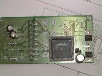
Hate to disappoint, but your approach of using a ADC and feeding a 1 Bit DataStream back into the PWM digital modulator, has already been done – Rob Watts & I did back in early 2000 – and I’m sure others have done so earlier – its also Public domain as I demonstrated to many companies,
Below is a board I constructed using a FPGA as the modulator, ADC with an external 4th order loop.
It was complicated – but the sonic footprint of the ADC was always an issue – and did not qualify as a pure digital amplifier by my definition – measured performance was very good – only really needing a 3rd order loop around the ADC.
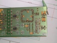
Below a picture of the only PCB I here in my lab in CZ (other exist somewhere), the DAC and Integrator OPAMP’s have since been removed…. The date on the PCB is 2000…..
John
Hate to disappoint, but your approach of using a ADC and feeding a 1 Bit DataStream back into the PWM digital modulator, has already been done – Rob Watts & I did back in early 2000 – and I’m sure others have done so earlier – its also Public domain as I demonstrated to many companies,
Below is a board I constructed using a FPGA as the modulator, ADC with an external 4th order loop.
It was complicated – but the sonic footprint of the ADC was always an issue – and did not qualify as a pure digital amplifier by my definition – measured performance was very good – only really needing a 3rd order loop around the ADC.
Below a picture of the only PCB I here in my lab in CZ (other exist somewhere), the DAC and Integrator OPAMP’s have since been removed…. The date on the PCB is 2000…..
John
Attachments
It's often said that ideas spring up independently in different people at roughly the same time.
I first started work on this in 1999, but never finished because the company was always "just interested enough" to keep us from selling it to outside parties but not interested enough to pay for the development. Further, the first attempt at writing a patent got botched by the patent attorney who reported that he "nearly understood the story, but would like to know what 'z' meant".
We had a second go in 2003.
I've got no idea what sound quality to expect from this, except that it's be the loop DAC determining the sound, mainly.
What I don't get is what you needed a 4th order loop around the ADC for. I had mine running at 768fs (=same as the modulator clock frequency. PWM frequency = 8fs) and 2nd order was more than enough for that. If you have a 4th order analog loop you lose the chip area advantage, and it really becomes more sensible to use that very same 4th order loop for the amp itself, and use the DAC, well, as DAC (as per your current approach).
From this difference in ADC design I suspect that there must be a few other differences between your work then and mine as well. If you could elaborate.
Hi Bruno,
I should have said 4th order to form the ADC….. Yep your correct 2nd order would probably have been enough, As I said earlier, in the end I used 3rd – to insure some correction “headroom” – the PCB was designed before I had any real idea how much correction I would need… hey, could have designed to 6th…..
It’s a long time since I worked in this method – I seem to recall the PWM Fs was about 1.5MHz – 2MHz to be above the AM band!!! Still the dissipation was not too bad – not too good
Later designs used reduced PWM clock rates…. Have to learn somehow….
Shame we did not know of each other back then – could have made a great team!
Hey, our modulator also operated at 768fs!!! parts of this early development became the Zetex ZXCW6100/8100 modulator (which has "un-published" modes and interface that would have linked to a second "analogue" driver / FB chip incorporating the integrators etc. That’s why the ZXCW6100 operates at such a high clock rate…… it was not really designed as a “stand alone” modulator – needed its companion….
John
- Status
- This old topic is closed. If you want to reopen this topic, contact a moderator using the "Report Post" button.
- Home
- Amplifiers
- Class D
- Difference betweeen Class D and "Digital Amplifiers"