ghemink said:
With 0V at the input of the Sg3525, nothing will happen, it will have 0 output. The sg3525 starts to work from about 0.9V at its input, I think it will give a 50% duty cycle at around 2V in or so. Effectively, the duty cycle will be almost 100%, so output voltage would be about 130V, this will blow my caps and I don't want to try that.
I will soon try to modify the feedback loop in the simplest possible way. Not adding an zero, just keep it as it is, just increase the size of the cap in the feedback loop to compensate for the lower resonance frequency of the LC filter with the bigger output cap. This should then still work with the original caps as well.
Best regards
Gertjan
OK, here are the results. I added a cap of 0.47uF in parallel to C25 see the schematics at:
http://www.a-and-t-labs.com/K6_Sw_Amp/index.htm
This moves the compensating zero in the compensation network from 100Hz down to 33Hz, this is about the factor 3 that the resonance frequency of the LC output filter would go down with a 10.000uF cap at the output.
I measured the smps with the default setting and with the added compensation cap with the default output caps and with an additional 8200uF cap at each rail. Plan to use high grade caps for that, but now just used a few caps that were lying around (so not super high quality).
The results are very good. The SMPS is completely stable with and without the added cap, as expected of course. Of course, the feedback loop reacts slower to any load changes, but it recovers very gentle, no overshoots, so lots of phase margin. I could increase the gain (have not done that), to reduce the 100Hz ripple more.
I heated up my dummy loads and went as high as 5.3A load. The output voltage stayed stable at about 63.8V at any load between 0.38A and 5.3A, at 5.3A we are talking 675W power, the dummy load got pretty hot.
The 100Hz ripple at the highest load of 5.3A was about 1.9V peak/peak, so about 670mV RMS with the standard caps and went down to 660mV peak/peak or 230mV RMS with the added 8200uF caps. So I got about a factor 3 reduction in 100Hz ripple.
The HF ripple consisting of mainly 150kHz and a smaller 75kHz component reached about 250mV peak/peak at 5.3A and is about 100mV peak/peak at 3A and lower.
I'm already very happy with this performance, I will in a later stage hook up my Elna Cerafines and I will also try to increase the gain since I'm sure I have a lot of phase margin. Possibly with the Elna's the HF ripple is further reduced. I can also play with some additional black gates that I have to see if I can reduce that HF ripple further. Besides that, I also have the white noise active supplies that I could hookup after the SMPS, expect than a super clean output without any 100Hz ripple and without any HF ripple (hopefully
") ).
).Maybe in the weekend or later next week, I plan to hook it up to a couple of UcD40 amps.
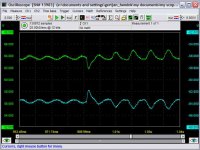
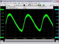
Attached are two scope measurements for the default case and the case with added 8200uF per rails. The load is switched from 164 Ohm to 41 Ohm, so from about 0.75A to about 3A. Note that the scales are blown up big time to 2V per division in both cases. Both + and - rails are shown.
Looks quite good I think.
Best regards
Gertjan
Attachments
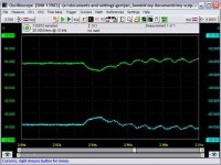
ghemink said:This is with the 8200uF caps.
I know which one I prefer
In case anybody wonders, the scope is a PC based scope with 12 bit resolution up to 50MHz sampling and 8 bit up to 100Mhz. It can do up to 14 bit and 16 bit resolution at lower sample frequencies (it uses oversampling). The scope is the HS3-100 from http://www.tiepie.nl (but better buy it in the US, a lot cheaper than in Europe). It also has an AWG (arbitrary waveforg generator) that is a great tool that I used to generate signals for the open loop measurements, no seperate generator needed, very nice.
Best regards
Gertjan
K6PS
I'm delighted to see DIY so alive and well, and the design changes/ improvemnts being undertaken! Very interesting!
FYI, one simplification that a builder told me about, as they adapted the design to their application, was to eliminate the op amps in the feedback loop, and fed the positive output directly to the SG3525 (via a filter network). The reason for the op amps is to regulate on both the positive and negative outputs of the supply. In retrospect, given that most audio loads are symetric on average, this was an excessively complicated approach.
Ironically, I sell far more stand-alone K6 power supplies than the amps - a bit surprising, as the design intent of the supply was only weight reduction, while the K6 amp was intended to be the star. They do really well in listenning tests, even compared to the $xK stuff out there. Oh well!
Reinhard
Re: K6PS
Hello Reinhard,
Well for some applications, it maybe nice to have the feedback from both rails as you have implemented it, in many cases both rails are not equally loaded (especially with Class D amps). Nice thing is also that you limit the maximum voltage from each rail that goes into the feedback network by the added zener diodes. This could actually be nice when used with class D amps since power supply pumping may occur and result in a higher rail voltage on one of the rails. As a result, the other rail would go down excessivly when trying to compensate for the rail that is being pumped up. Because of this, power supply pumping potential, I wanted to use bigger caps. Probably for use with AB amps, the default configuration is good enough. However, taking feedback from only one rail, is probably even tricky with class AB amps.
I also like the current limiting function, have not tried it yet would need to heat up my dummy loads and then switch on some lightbulbs in addition to that. Don`t know whether I`m going to try that.
So I would say, don`t simplify the design, I think the features it has now and the feedback taken from both rails are desired. I just did not like the overshoot during startup. The output went up to about 77V or so before settling at about 63.5V (had expected 58V), so using it with 63V caps is a no-go (the 77V surge maybe too much). So I added the RC filter for Vref that solved it. However, it is not the complete solution, when the protection kicks in, Vref will probably stay as it is, so when it comes back out of protection, I likely will have the same overshoot. I`m thinking of adding a few components to discharge the C of the RC filter when the protection kicks in, then after that, the supply should recover nicely even after a shutdown due to overload.
I was wondering whether you have some special reason not to use the error amp that is built in in the SG3525?
I will optimize the feedback network further as with the bigger caps, the Q factor of the LC filter goes down, so phase margin is increased because of that. I also use it at 60V while it is designed to be used over a range of 40 to 82V. The 60V case should have more phase margin than the 40V case, so I can get some (3-4dB) gain from that as well. On top of that, the mains voltage in Japan is only 100V, giving margin as well (plan to keep that as additional margin).
I`m tempted to try adding an additional zero in the feedback network. The additional zero improves phase margin and allows thus more gain and even more suppression of the 100Hz mains related ripple. It would also reduce the voltage drop after a sudden load change. Don`t want to overdo it. I don`t want to increase the gain at high frequencies (say above 20kHz or so) to avoid that the switching noise can have a negative influence on the feedback loop. So plan to use that 2nd zero (and pole) in a moderate way.
Best regards
Gertjan
rmetz said:I'm delighted to see DIY so alive and well, and the design changes/ improvemnts being undertaken! Very interesting!
FYI, one simplification that a builder told me about, as they adapted the design to their application, was to eliminate the op amps in the feedback loop, and fed the positive output directly to the SG3525 (via a filter network). The reason for the op amps is to regulate on both the positive and negative outputs of the supply. In retrospect, given that most audio loads are symetric on average, this was an excessively complicated approach.
Ironically, I sell far more stand-alone K6 power supplies than the amps - a bit surprising, as the design intent of the supply was only weight reduction, while the K6 amp was intended to be the star. They do really well in listenning tests, even compared to the $xK stuff out there. Oh well!
Reinhard
Hello Reinhard,
Well for some applications, it maybe nice to have the feedback from both rails as you have implemented it, in many cases both rails are not equally loaded (especially with Class D amps). Nice thing is also that you limit the maximum voltage from each rail that goes into the feedback network by the added zener diodes. This could actually be nice when used with class D amps since power supply pumping may occur and result in a higher rail voltage on one of the rails. As a result, the other rail would go down excessivly when trying to compensate for the rail that is being pumped up. Because of this, power supply pumping potential, I wanted to use bigger caps. Probably for use with AB amps, the default configuration is good enough. However, taking feedback from only one rail, is probably even tricky with class AB amps.
I also like the current limiting function, have not tried it yet
would need to heat up my dummy loads and then switch on some lightbulbs in addition to that. Don`t know whether I`m going to try that. So I would say, don`t simplify the design, I think the features it has now and the feedback taken from both rails are desired. I just did not like the overshoot during startup. The output went up to about 77V or so before settling at about 63.5V (had expected 58V), so using it with 63V caps is a no-go (the 77V surge maybe too much). So I added the RC filter for Vref that solved it. However, it is not the complete solution, when the protection kicks in, Vref will probably stay as it is, so when it comes back out of protection, I likely will have the same overshoot. I`m thinking of adding a few components to discharge the C of the RC filter when the protection kicks in, then after that, the supply should recover nicely even after a shutdown due to overload.
I was wondering whether you have some special reason not to use the error amp that is built in in the SG3525?
I will optimize the feedback network further as with the bigger caps, the Q factor of the LC filter goes down, so phase margin is increased because of that. I also use it at 60V while it is designed to be used over a range of 40 to 82V. The 60V case should have more phase margin than the 40V case, so I can get some (3-4dB) gain from that as well. On top of that, the mains voltage in Japan is only 100V, giving margin as well (plan to keep that as additional margin).
I`m tempted to try adding an additional zero in the feedback network. The additional zero improves phase margin and allows thus more gain and even more suppression of the 100Hz mains related ripple. It would also reduce the voltage drop after a sudden load change. Don`t want to overdo it. I don`t want to increase the gain at high frequencies (say above 20kHz or so) to avoid that the switching noise can have a negative influence on the feedback loop. So plan to use that 2nd zero (and pole) in a moderate way.
Best regards
Gertjan
Sorry, Ghemink, I told you to put the input of the SG3525 to GND in order to get 50% duty cycle because I usually connect the non inverting input to the reference and use the inverting one to control. So if you tie the inverting input to GND you get full output. I have just realized that the K6 SMPS input is non-inverting. That's why you have to put more than 2 volts there to get full duty-cycle output (ooops).
If you would get +/-130V with that output, I understand that you don't want to make the test, of course!
BTW: How hot does the PSU get with that 650W continous output? Are you using an additional heatsink or only the bracket shown in the webpage? Have you measured efficiency? (I know, difficult with offline supplies without PFC)
Best regards,
Pierre
Pierre said:Sorry, Ghemink, I told you to put the input of the SG3525 to GND in order to get 50% duty cycle because I usually connect the non inverting input to the reference and use the inverting one to control. So if you tie the inverting input to GND you get full output. I have just realized that the K6 SMPS input is non-inverting. That's why you have to put more than 2 volts there to get full duty-cycle output (ooops).
If you would get +/-130V with that output, I understand that you don't want to make the test, of course!
BTW: How hot does the PSU get with that 650W continous output? Are you using an additional heatsink or only the bracket shown in the webpage? Have you measured efficiency? (I know, difficult with offline supplies without PFC)
Best regards,
Pierre
Hi Pierre,
I'm still using that small L profile only. I don't test for long times with large loads because my load resistors would probably burn out before the SMPS would. Of course it needs some heat sinking. Once I finish tweaking the performance. I plan to mount it to a bigger L profile that will be mounted to an aluminum plate (bottom of the case). I hope that is enough cooling since it will probably never need to run at full power for long times. I will use high efficiency class D amps and I never listen to dynamically compressed music, so average power is probably well below 100W. If more heatsinking needed, I will do that of course.
I don't know about the efficiency, I may measure it in the future but it is very low on my priority list. My priority is on performance and the main reason to use a SMPS was to get a regulated supply without the need of too bulky cooling that would be needed for a conventional series regulator.
Best regards
Gertjan
So, if I get it right, in a non regulated SMPS, (always at max. duty cycle), the output inductors could be low valued, for example 5-10uH, with big capacitors, several thousands uF, right?
I think that that's the idea most car audio amplifiers use. Even if some of them are regulated, there is no necessity for a so wide range in duty cycles as K6 SMPS (and others) uses, as the car supply varies only between 11 and 14V aprox, and doesn't need to cope with 100 to 240V to cover worldwide mains. So with a narrower input range, a less varying duty cycle can be used and hence the transformer can be optimized for almost 50% duty cycle, so the output inductors can be reduced to a few uH.
Just thinking in loud...
Pierre said:So, if I get it right, in a non regulated SMPS, (always at max. duty cycle), the output inductors could be low valued, for example 5-10uH, with big capacitors, several thousands uF, right?
I think that that's the idea most car audio amplifiers use. Even if some of them are regulated, there is no necessity for a so wide range in duty cycles as K6 SMPS (and others) uses, as the car supply varies only between 11 and 14V aprox, and doesn't need to cope with 100 to 240V to cover worldwide mains. So with a narrower input range, a less varying duty cycle can be used and hence the transformer can be optimized for almost 50% duty cycle, so the output inductors can be reduced to a few uH.
Just thinking in loud...
You maybe right, I'm not an expert on SMPS. In a car, you probably have a pretty stable battery that is stronger than the 100V mains that I have here in Japan. So regulation may not be needed. I can't answer on whether a small L in combination with a big C is ok in such a case.
I prefer large L and large C
Best regards
Gertjan
ghemink said:This is with the 8200uF caps.
I know which one I prefer
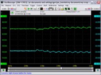
And this one is with the original 0.22uF cap but now resistor R25 changed from 7k to 33k. This increases the gain and reduces the frequency of the first zero needed to keep things stable with the big 8200uF caps. The gain can be increased because the LC filter output essentially falls of with 6dB/Oct due to the low Q factor and due to the series resistance of the cap itself (0.05Ohm). I tried even higher values, but then at high currents (more than 5A), you get a slight oscillating behavior, not heavy, but larger than the 100Hz ripple. Everything stayed clean up to 43k, but when I switched to 56k, I got some weak oscillations at about 250Hz when switching from the 41 Ohm load to the 23.4 Ohm load (from about 3A to 5.5A). With 56k, the 3A load gives no problem at all. For safety I decide to use 33k to have a safe margin for even higher currents.
When I hook up the elna caps I may have to do this exercise again because the elna's probably have a lower series resistance.
Note that the drop due to the switching in the load is now almost invisible (switching from 0.8A to about 3A).
Attachments
ghemink said:
And this one is with the original 0.22uF cap but now resistor R25 changed from 7k to 33k. This increases the gain and reduces the frequency of the first zero needed to keep things stable with the big 8200uF caps. The gain can be increased because the LC filter output essentially falls of with 6dB/Oct due to the low Q factor and due to the series resistance of the cap itself (0.05Ohm). I tried even higher values, but then at high currents (more than 5A), you get a slight oscillating behavior, not heavy, but larger than the 100Hz ripple. Everything stayed clean up to 43k, but when I switched to 56k, I got some weak oscillations at about 250Hz when switching from the 41 Ohm load to the 23.4 Ohm load (from about 3A to 5.5A). With 56k, the 3A load gives no problem at all. For safety I decide to use 33k to have a safe margin for even higher currents.
When I hook up the elna caps I may have to do this exercise again because the elna's probably have a lower series resistance.
Note that the drop due to the switching in the load is now almost invisible (switching from 0.8A to about 3A).
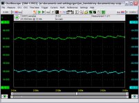
And here when switching from 3A to 5.4A load. The switching oocurs at about 2.59s, can not see it.
Attachments
ghemink said:
And here when switching from 3A to 5.4A load. The switching oocurs at about 2.59s, can not see it.
And here is the AC residue on the power rail (only positive rail shown).
About 400mV peak/peak LF residue (100Hz + harmonics) and only about 40mV peak/peak for the HF residues. And this is at a load of 5.4A on both rails with both rails at 64V, so delivering 690W power.
I think I have a hell of a power supply here that is immune to changes in the load current and has very low LF and HF ripple.
Thanks to Reinhard for this supply that I could further optimize in a relatively simple way. Hopefully this weekend, I can hook up some of my UcDs to see how it works with the amps.
Best regards
Gertjan
Attachments
Jan-Peter said:Gertjan,
Big compliments!!!
Looks very goods. This would be pronably the ultimate kit, SMPS and an UcD400.
Or the UcD700 hopefully top be released before summer
Regards,
Jan-Peter
The only thing remaining to be tested is power supply pumping issues when used with unbridged UcD modules. I plan to bridge two UcDs for my woofer amps, so then it is OK. However, I plan to test it with a single UcD and blow 20Hz at a few hundred watt in my poor dummy loads
and see what happens.Best regards
Gertjan
ghemink said:
The only thing remaining to be tested is power supply pumping issues when used with unbridged UcD modules. I plan to bridge two UcDs for my woofer amps, so then it is OK. However, I plan to test it with a single UcD and blow 20Hz at a few hundred watt in my poor dummy loads
Best regards
Gertjan
I've been follwing this thread with great interest. Have you tried the above test yet? How did it go? Also, did you try listening with the stock SMPS connected to the UCD400?
Good work, and looking forward to your ongoing posts. As someone without the necessary instruments or technical knowledge to do what you're doing, I appreciate the posting of your results here.
Thanks,
Greg
GregD said:
I've been follwing this thread with great interest. Have you tried the above test yet? How did it go? Also, did you try listening with the stock SMPS connected to the UCD400?
Good work, and looking forward to your ongoing posts. As someone without the necessary instruments or technical knowledge to do what you're doing, I appreciate the posting of your results here.
Thanks,
Greg
Hi Greg,
Thanks for the interest.
I have not done those tests yet. Was a bit busy at my regular work. I plan to modify more but before that I plan to take some power supply pumping measurement tests with the UcD400 modules. I`ll probably have some time for further experimenting next week. I`ll keep reporting here.
A couple of things on the list for further improvements:
1. improve startup behavior further (have ideas for that)
2. look at the recovery after a shutdown and improve it. I have not checked this but I expect to get an overshoot of the output voltage after the SMPS shuts down (either manually forced or due to overcurrent).
3. Add more caps and using R-C-R T type of connection with for example 4 caps in parallel with each their own R`s (i.e. 0.2Ohm), this may not be in interest of most users, but I already have a large stock of 63V 8200uF caps that I had originally bought for a conventional supply.
4. add remote sensing, meaning, have the SMPS in a seperate case than the amps but take the feedback signal from the power supply pins on the UcD modules. Thus cancelling series resistance due to connectors etc. Remote sensing can be tricky (stability etc), however, the feedbacl loop operates at relatively low frequencies so maybe not that much of an issue. I also plan to keep some local sensing so that even when the remote sensing loop is not present, i.e. cable disconnected, that the output voltage does not go sky-high.
All the above may make it a bit of a long project so I`ll first connect some UcD modules to look at pumping and to check how it sounds with my woofers. I plan to use it in bridge, so pumping is never and issue but in the interest of others, I`ll give it a try with an unbridged UcD as well.
If I`m really in a bad mood, I may want to compare it with a conventional supply, I have however only 300W trannies that I`m now using to feed UcD180 amps, so those trannies will loose big time. Also with the current level of ripple, you would need a conventional supply with much more caps at the output. A 400mV drop in 10ms (100Hz ripple) with 5A load corresponds with a cap of 125.000uF!!! While I only have about 9.000uF total at the output at this moment. The current spikes that you draw from the mains with such a bizar cap (125.000uF) will also be quite bizar.
I don`t have a current clamp at the moment, so can not measure the mains current, plan to do that in the future (low priority).
Best regards
Gertjan
How do you think an unmodified K6 power supply would work/sound with the UCD400? Any thoughts compared to what I've tried below?
The combinations I've tried with my UCD400s in a monobloc configuration used 625VA and 1500VA transformers with a range of filter capacitors from 40,000uf to 328,000uf per amplifier. I noticed a difference between the two transformers with the larger one sounding more effortless and smoother. I didn't notice much difference going from 40,000uf to 80,000uf, but there was a difference when I went to 164,000uf with the sound becoming a little more natural and a bit less sharp. If there was a difference going to 328,000uf, I couldn't hear it.
The problem is that 1500VA transformers, 164,000uf of capacitors, and the associated parts are big and heavy, but I'm unwilling to compromise the sound for this reason. Do you think that the K6 power supply could sound as good or better than what I've tried so far?
GregD said:How do you think an unmodified K6 power supply would work/sound with the UCD400? Any thoughts compared to what I've tried below?
The combinations I've tried with my UCD400s in a monobloc configuration used 625VA and 1500VA transformers with a range of filter capacitors from 40,000uf to 328,000uf per amplifier. I noticed a difference between the two transformers with the larger one sounding more effortless and smoother. I didn't notice much difference going from 40,000uf to 80,000uf, but there was a difference when I went to 164,000uf with the sound becoming a little more natural and a bit less sharp. If there was a difference going to 328,000uf, I couldn't hear it.
The problem is that 1500VA transformers, 164,000uf of capacitors, and the associated parts are big and heavy, but I'm unwilling to compromise the sound for this reason. Do you think that the K6 power supply could sound as good or better than what I've tried so far?
Hi Greg,
With an unmodded K6 supply there are only two 470uF caps per rail, so about 1000uF. This will very likely not be enough to prevent power supply pumping. Besides that, the 100Hz ripple voltage with the unmodded version would be quite large, probably comparable with a conventional supply with something like 4700uF caps. So in comparison with an unmodded K6, your power supplies will be better in terms of stability. But what you have there is quite bizar. The nice thing of the SMPS is that due to the feedback, with the same amount of caps at the output, the ripple can be far less (about a factor 10 or so depending on the amount of feedback). So if I would hook up like 100.000uF to the SMPS, the ripple would be like that of a conventional supply with 1F caps.
Maximum I`m planning to hook up something like 4x8200uF via 4 R-C-R T networks and at the end a 10.000uF ELNA Cerafine to top it off. This should reduce the HF ripple (that is already very small) even further. This would then give a total of more than 40.000uF at the output. I`m sure this is absolutely a bizar amount of overkill, however, I have the caps, so why not use them. For normal use, I think this SMPS with one good quality 10.000uF cap and the modded feedback performs good enough (based on measurements). Have to do listening tests of course.
Best regards
Gertjan
shutdown behavior
I restored the supply that I have to almost its original state (kept the RC network that ramps up Vref nicely to avoid the overshoot at startup).
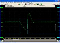
Then I had a look at the shutdown behavior. I applied a 100ms pulse at the shutdown input. In that case, the supply should shutdown and opamp IC2 should function is a latch to keep the shutdown state for a while until the latched state is reset by R24, C9 and Q5 combination. However, it turned out that after the pulse, the supply starts immediately, well before the sofstart cap C6 is discharged. So, the supply restarts at full power. As a result, the overcurrent protection of the supply is triggered a couple of times during the charging of the output caps (the 2x470uF per rail). The output signal is really nasty, see attachment. The blue signal is the signal at the shutdown pin, the green signal is the + rail output voltage. The + rail goes all the way up to 110V!!!! after the restart after the shutdown pulse goes low. The ripple on the output voltage directly after restart is because during that ramp up, the overcurrent detection of the supply trips a couple of times, shutting down the supply for short periods of time. The supply was loaded with a 164 dummy load between + and - rail.
Because of the nasty restart I decided to remove Q5 since I expected that this one resets the latched state too fast. In that case, IC2 should always stay in the latched state, so no restart. I think for safety I would prefer this. After an overcurrent situation or a shutdown, the supply would stay in the shutdown state. One would have to remove the mains voltage to reset the supply, this is of course the safest approach. However, this did not change anything. So conclusion, IC2 that has to function as a latch circuit, does not work as a latch.
After more measurements, I found out that the reason why IC2 is not working as a latch is that the output of IC2 is loaded too heavy. A LED is connected to that output with a 316 Ohm resistor. This alone draws about 30mA, it has some other load at the output as well, so that poor opamp's output voltage dropped quite a bit and became too low to make it function as a latch. When I replaced the 316Ohm resistor R40 with a 1k resistor, the latch worked perfectly and the output voltage had some margin to let the latch work properly.
After I found this al out, I did not replace Q5 anymore, in fact, Q5 was damaged when I desoldered it. But that is OK, I can check it with the other supply that I have not build yet. But I think I keep it this way, no restarts after a shutdown or overload is the safest approach anyway. I plan to add bigger output caps as I experimented with before, so with those bigger caps, output current peaks should be no problem and should not trip the overcurrent detection circuit of the supply too fast.
Bottomline of the whole story is that this shutdown circuit does not work correctly, R40 needs to be replaced with a 1k resistor to make things work. I think this is quite a serious thing and users should be aware of this not corectly functioning shutdown circuit. I assume the supplies of other users will have the same issue. Note that my supplies came with LM358 for IC2, the original schematic shows LM258, don't think that these opamps are a lot different.
Best regards
Gertjan
I restored the supply that I have to almost its original state (kept the RC network that ramps up Vref nicely to avoid the overshoot at startup).
Then I had a look at the shutdown behavior. I applied a 100ms pulse at the shutdown input. In that case, the supply should shutdown and opamp IC2 should function is a latch to keep the shutdown state for a while until the latched state is reset by R24, C9 and Q5 combination. However, it turned out that after the pulse, the supply starts immediately, well before the sofstart cap C6 is discharged. So, the supply restarts at full power. As a result, the overcurrent protection of the supply is triggered a couple of times during the charging of the output caps (the 2x470uF per rail). The output signal is really nasty, see attachment. The blue signal is the signal at the shutdown pin, the green signal is the + rail output voltage. The + rail goes all the way up to 110V!!!! after the restart after the shutdown pulse goes low. The ripple on the output voltage directly after restart is because during that ramp up, the overcurrent detection of the supply trips a couple of times, shutting down the supply for short periods of time. The supply was loaded with a 164 dummy load between + and - rail.
Because of the nasty restart I decided to remove Q5 since I expected that this one resets the latched state too fast. In that case, IC2 should always stay in the latched state, so no restart. I think for safety I would prefer this. After an overcurrent situation or a shutdown, the supply would stay in the shutdown state. One would have to remove the mains voltage to reset the supply, this is of course the safest approach. However, this did not change anything. So conclusion, IC2 that has to function as a latch circuit, does not work as a latch.
After more measurements, I found out that the reason why IC2 is not working as a latch is that the output of IC2 is loaded too heavy. A LED is connected to that output with a 316 Ohm resistor. This alone draws about 30mA, it has some other load at the output as well, so that poor opamp's output voltage dropped quite a bit and became too low to make it function as a latch. When I replaced the 316Ohm resistor R40 with a 1k resistor, the latch worked perfectly and the output voltage had some margin to let the latch work properly.
After I found this al out, I did not replace Q5 anymore, in fact, Q5 was damaged when I desoldered it. But that is OK, I can check it with the other supply that I have not build yet. But I think I keep it this way, no restarts after a shutdown or overload is the safest approach anyway. I plan to add bigger output caps as I experimented with before, so with those bigger caps, output current peaks should be no problem and should not trip the overcurrent detection circuit of the supply too fast.
Bottomline of the whole story is that this shutdown circuit does not work correctly, R40 needs to be replaced with a 1k resistor to make things work. I think this is quite a serious thing and users should be aware of this not corectly functioning shutdown circuit. I assume the supplies of other users will have the same issue. Note that my supplies came with LM358 for IC2, the original schematic shows LM258, don't think that these opamps are a lot different.
Best regards
Gertjan
Attachments
- Status
- This old topic is closed. If you want to reopen this topic, contact a moderator using the "Report Post" button.
- Home
- Amplifiers
- Class D
- A and T labs K6 SMPS for Class D amp use