I just made an experiment classD, and failed. It's quite different than building analog amps. I think I have to learn from basic again. The aim is good sounding offcourse 
What is the difference (technically and sonically) between
1. ClassD made by full discrete (like UCD) and classD made by IC's (like IRFaudio)?
2. ClassD that takes feedback before LC filter and classD taking feedback after LC filter?
3. How bad is phase shifts made by LC filter? Why manufacturers like IRF and LT takes feedback before LC, while majority here likes to take feedback after LC filter? Pro's and Con's?
Hi lumanauw, I am just going to ramble off some thoughts quickly as your questions do not have simple answers. Feedback after the filter tends to give lower distortion since filter nonlinearities are compensated for by feedback. A good discrete class D amp can give lower distortion if it is done so that it can almost operate cleanly in linear mode.
I think an amp made largely of IC chips can be done to give clean output as well, but it tends to be harder to eliminate discontinuities in the signal flow. Whenever the signal has to jump between on-off thresholds, distortion increases--the greater and/or slower the jump, the more distortion there tends to be. But, consistency or smoothness in signal flow may be more useful than pure propagation speed of the signal through the amp. Those are some quick thoughts.
I am still working on a P/N design. I am having trouble getting my pspice models for the IRF9540n and IRF540n to give me accurate simulations, though.
Hi subwo1 !
Welcome to the club, i also can't simulate with irf540n/9540n,
but wanted to use them for my P/N-ClassD (fully discrete).
The models from IRF don't really work in pspice...
Lumanauw, if you want to design dicrete ClassD, you will need
simulations. It's too hard to predict deadtimes/crossconductions,
rise/fall-times. I don't really trust sims at these speeds, but they
give a good idea.
Mike
Hi, Subwo1,
I reallly wonder why large manufacturer with deep knowledge in switching like IRF takes the feedback before the LC, assuming they know that they can take the feedback after LC.
Hi, Mike,
How far is the phase shift made by LC filter? Will it making the front end/comparator/differential receiving the correct signal for NFB correction?Feedback after the filter tends to give lower distortion since filter nonlinearities are compensated for by feedback
I reallly wonder why large manufacturer with deep knowledge in switching like IRF takes the feedback before the LC, assuming they know that they can take the feedback after LC.
Hi, Mike,
Yes, in this case, SIM is a must. With analog amps, we can get without SIM, but not in this field, I think.Lumanauw, if you want to design dicrete ClassD, you will need simulations. It's too hard to predict deadtimes/crossconductions, rise/fall-times. I don't really trust sims at these speeds, but they give a good idea.
Hi,
Naaaaah, sounds like you got something out of it, right? That's not a failure.
I would say start with the class d reference design thread, lots of good stuff in there for ya.
Sims are a total pain but if you get good with one you can do some neat things, and lots of experimentation rather cheaply.
IR just arent' in the amp design business so much as mosfets + drivers.
Regards,
Chris
I just made an experiment classD, and failed.
Naaaaah, sounds like you got something out of it, right? That's not a failure.
I would say start with the class d reference design thread, lots of good stuff in there for ya.
Sims are a total pain but if you get good with one you can do some neat things, and lots of experimentation rather cheaply.
IR just arent' in the amp design business so much as mosfets + drivers.
Regards,
Chris
lumanauw said:How far is the phase shift made by LC filter? Will it making the front end/comparator/differential receiving the correct signal for NFB correction?
Hi, it may appear that way at first, and to a point, if the delay is really great by using, say, a 100uH inductor, then maybe it will cause problems with filter resonance getting too close to the audio range.
From the opposite perspective, the filter tends to limit how many harmonics can rechurn through the amp. So the sound may actually gain smoothness and fidelity.
An advantage of feedback before the filter would seem to be that it is easier to get really high switching frequencies without producing more high frequency switching content at the output. I don't really see why it should not also benefit from fewer harmonics as well. I may be missing something with these thoughts on harmonics. Best Regards.
Hi again, indeed, I was overlooking at least one thing about after filter feedback. The phase lead (compensation) can keep the input and output pretty much in net phase over a full switching cycle. The input gets ahead for half a cycle and then behind for the other half. So I doubt with a switching frequency of a few hundred kilohertz the ear has any chance of perceiving the back and forth time difference.
Hi, Subwo1,
I see majority of self-oscilating designs here are using after LC feedback point (with some exceptions, like IRF amp). From the IRF paper, fig 7 of iraudamp1.pdf, the red curve is peaking. They write that peaking is due to resonance of LC filter.
Will the amp which take feedback after LC do not have this?
How about sonics and stability comparison of feedback after LC and before LC. Any member here have made both?
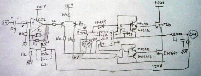
This is my experimental classD. The feedback is taken after LC. I use IR2111 driver, I have clean square drive now (but in higher frequency, the square have oscilation/ringing in the edges)
Without R1,C2,R3,C3, the oscilation frequency is about 24khz. When I put 10k for R1, the oscilation frequency rises alot, but the square is ringing in edges, so I lowered the frequency by putting 1k for R3 and 220pf for C3.
I cannot put R3 and C3 in parrarel with feedback resistor (C2 place) like UCD patent. If I put it there (or just a single C2=100pf), all the mosfets blown.
There are things that I dont understand about L1 and C1 value.
If I put L1=200uH and C1=220uF (nonpolar Elko), the amp looks normal, but cannot drive high volumes. The sound is wrecked. In low volume, seems fine.
If I put L1=30uH and C1=2.2uF (WIMA MKP), the mosfets blows instantly (upper and down mosfets, all blown)
If I put L1=30uH and C1=47uF (nonpolar elko), or C1=220uF(elko), the elkos and L are heating up very quickly, and the current draw at idle rises alot.
If I put L1=200uH and C1=47uF (nonpolar elko), both the L and C heating up.
I wonder how come the designs here uses L only 40uH and C only 1uF without problem for self oscilating classD?
Seems I cannot have that low values of L and C. How to do that? Is this value of 40uH and 1uF valid only on switching frequency >300khz? My current is only 40khz, none of these low value can work. I've tried to raise the frequency by not using R3 and C3, but the idle current is very high, I shut down the arrangement imediately.
I've blown many-many IRF640 today.
I see majority of self-oscilating designs here are using after LC feedback point (with some exceptions, like IRF amp). From the IRF paper, fig 7 of iraudamp1.pdf, the red curve is peaking. They write that peaking is due to resonance of LC filter.
Will the amp which take feedback after LC do not have this?
How about sonics and stability comparison of feedback after LC and before LC. Any member here have made both?
This is my experimental classD. The feedback is taken after LC. I use IR2111 driver, I have clean square drive now (but in higher frequency, the square have oscilation/ringing in the edges)
Without R1,C2,R3,C3, the oscilation frequency is about 24khz. When I put 10k for R1, the oscilation frequency rises alot, but the square is ringing in edges, so I lowered the frequency by putting 1k for R3 and 220pf for C3.
I cannot put R3 and C3 in parrarel with feedback resistor (C2 place) like UCD patent. If I put it there (or just a single C2=100pf), all the mosfets blown.
There are things that I dont understand about L1 and C1 value.
If I put L1=200uH and C1=220uF (nonpolar Elko), the amp looks normal, but cannot drive high volumes. The sound is wrecked. In low volume, seems fine.
If I put L1=30uH and C1=2.2uF (WIMA MKP), the mosfets blows instantly (upper and down mosfets, all blown)
If I put L1=30uH and C1=47uF (nonpolar elko), or C1=220uF(elko), the elkos and L are heating up very quickly, and the current draw at idle rises alot.
If I put L1=200uH and C1=47uF (nonpolar elko), both the L and C heating up.
I wonder how come the designs here uses L only 40uH and C only 1uF without problem for self oscilating classD?
Seems I cannot have that low values of L and C. How to do that? Is this value of 40uH and 1uF valid only on switching frequency >300khz? My current is only 40khz, none of these low value can work. I've tried to raise the frequency by not using R3 and C3, but the idle current is very high, I shut down the arrangement imediately.
I've blown many-many IRF640 today.
Attachments
Hi lumanauw,
With suitable phase compensation and a sufficiently high switching frequency, and so long as the output does not clip and the input signal does not change too much too quickly, then post filter feedback can enable the amp to damp output filter resonance. There are many ifs; its true.
I'd say the turn-on time is too fast, and there may also be a lot of gate ringing. The turn-on portion of each MOSFET driver buffer needs some resistance. I'd try separating the emitters, placing a 10 to 20 ohm or so resistor between them. Connect the intersecting point between the PNP emitter and the resistor to the gate.
I can only try to give some general guesses about the types of things that are happening since I can't tinker with the actual circuit. If you can, try to set up a simulation model of your circuit in LTspice so that you can compare the two and maybe get some ideas.
In some filter combinations, I suspect one or two things could be happening. One is that the filter could be going into heavy resonance, and the other is that the inductor is saturating. It would seem to be most likely with the 30uH unless it is air core, but especially then it could be inducing interference into your circuit. But a saturating core will overload and overheat your MOSFETs and cause them to blow.
One reason is that a high switching frequency permits the inductor impedance to remain high enough. The general answer to excessive power consumption during higher switching frequencies is switching losses. These can be causes by switching on one MOSFET too quickly after the other has turned off. Maybe the added gate resistor will help that problem. Sorry about the string of dead MOSFETs.
If you are going to get a functional amp, the IR2111 IC is a relatively easy path to that goal. I am confident you can get it to work! Best regards.
...peaking. They write that peaking is due to resonance of LC filter.
With suitable phase compensation and a sufficiently high switching frequency, and so long as the output does not clip and the input signal does not change too much too quickly, then post filter feedback can enable the amp to damp output filter resonance. There are many ifs; its true.
I have clean square drive now (but in higher frequency, the square have oscilation/ringing in the edges)
I'd say the turn-on time is too fast, and there may also be a lot of gate ringing. The turn-on portion of each MOSFET driver buffer needs some resistance. I'd try separating the emitters, placing a 10 to 20 ohm or so resistor between them. Connect the intersecting point between the PNP emitter and the resistor to the gate.
There are things that I dont understand about L1 and C1 value
I can only try to give some general guesses about the types of things that are happening since I can't tinker with the actual circuit. If you can, try to set up a simulation model of your circuit in LTspice so that you can compare the two and maybe get some ideas.
In some filter combinations, I suspect one or two things could be happening. One is that the filter could be going into heavy resonance, and the other is that the inductor is saturating. It would seem to be most likely with the 30uH unless it is air core, but especially then it could be inducing interference into your circuit. But a saturating core will overload and overheat your MOSFETs and cause them to blow.
I wonder how come the designs here uses L only 40uH and C only 1uF without problem for self oscilating classD?
Seems I cannot have that low values of L and C. How to do that? Is this value of 40uH and 1uF valid only on switching frequency >300khz? My current is only 40khz, none of these low value can work. I've tried to raise the frequency by not using R3 and C3, but the idle current is very high, I shut down the arrangement imediately.
One reason is that a high switching frequency permits the inductor impedance to remain high enough. The general answer to excessive power consumption during higher switching frequencies is switching losses. These can be causes by switching on one MOSFET too quickly after the other has turned off. Maybe the added gate resistor will help that problem. Sorry about the string of dead MOSFETs.
If you are going to get a functional amp, the IR2111 IC is a relatively easy path to that goal. I am confident you can get it to work! Best regards.
Hi, Subwo1,
Yes, it already produces sound (in low level), I guess this is a good start.
Anything weird in my schematic (besides the buffers you mentioned)? I've got no simulator, I make experiment by W2W connection.
Some questions :
1. Is it OK to use Elkos (elektrolit capacitor) for LC filter? Or MUST use non-elektrolit type (like WIMA or Mylar capacitor)?
2. I cannot use low valued L and low valued C (below 100uH and below 100uF). Where can I learn more about the design of LC filter of classD power amp?
My elkos and cores are heating very quickly in some values (low values). Something must be wrong in my experiment, since others here can use L<50uH + C<2.2uF without heat or current draw or other complain at all.
Hi lumanauw, I am going to guess that with low loss output filter capacitors like polypropylene, the filter Q is higher than the noise tolerance of your circuit can handle. The electrolytic ones are lossy and provide damping to the filter. Electrolytic capacitors commonly get hot at high frequencies.
Your cores heating at low inductance values indicates to me they are being subjected to too much magnetic flux and maybe even saturating. Lower switching frequencies let the flux on the core build up longer. Try the modified gate driver buffer first to see if it will let you raise the switching frequency so that you can try a lower valued inductor. You are right that your goal will be something on the order of a 40uH choke and a 1uF capacitor.
You may also try to adjust the positioning of your parts and incorporate anti-interference techniques like twisting together parallel runs of wires, especially if they constitute a closed circuit path. So, a "hot" and a return wire should be twisted when possible. Keep high frequency circuit paths short and tight. Place a poly .22uF or so decoupling capacitor directly from the drain of the upper MOSFET to the source of the lower. They should be very close to each other. Keep all component lead lengths as short as possible. I recommend using 1/8w resistors as the optimal size for low voltage p2p. You may like to try to to keep the circuits in tight sections like your own versions of integrated circuits. Component bodies may be touching when voltages present permit.
Here is your new simulator:
http://ltspice.linear.com/software/swcadiii.exe
It's free, full version, perfectly legal, is a decent program, sooner you get comfy with it the better, it will allow you to do all kinds of experimentation quickly and easily.
http://ltspice.linear.com/software/swcadiii.exe
It's free, full version, perfectly legal, is a decent program, sooner you get comfy with it the better, it will allow you to do all kinds of experimentation quickly and easily.

Hi David
At least the combinations with a large cap make for a low corner frequency and therefore a low switching frequency as well. But if we have a combination of 20 uH and more than 1 uF of capacity we do not only have a low cutoff frequency - we also have a highish Q and a very low inductance for an amp switching at low frequencies, giving quite a high idle current through the coil.
Do you have a scope to see how fast it actually switches or do you have access to one ?
Regards
Charles
Hi, Subwo1,
I've been using basing totem pole (without R) for years. I don't know if putting R in totem pole emitors is a must
The gate pulse are changing shape a bit. Before R it is full square, but after putting R, the left top edge is rounding.
Subwo1, what is the proper totem pole for classD should looks like? (driving parrareled mosfets with small capacity chip like IR2111).
Hi, Charles,
The switching frequency of my current setup is only 24khz. I can raise it to more than 100khz, but the gate pulses are ringing (blurry in scope), and the edges are ringing.
My switching frequency is only 24khz. It works with L=200uH and C=220uF. I've put 12V zeners to protect the G-S. But when I put small inductance (50uH) or small capacitor (2.2uF), all upper and down mosfets are blown instantly. What is making all the mosfets blown? The zeners are OK after blown, it means the destructive thing is not from the gate, but from somewhere else. But where does it comes from? Too much Idrain? The mosfets are not burning. They just becomes shorted G-D-S. I'm confused what is ruining the mosfets.
I dare not raising the frequency because I still feel something is wrong right now. The value of LC seems to have small connection to the switching frequency. It is determined more by feedback arrangements, global feedback+local feedback around opamp in my experiment amp.
Your suggestions seems improving my experiment amp. I put R=47ohm in the totem pole (after emitor of NPN), and it improves the max level that I can play this amp. Before putting this R, in medium level it already wrecked sound, but after putting this R, in the same volume it doesn't wrecked.I'd say the turn-on time is too fast, and there may also be a lot of gate ringing. The turn-on portion of each MOSFET driver buffer needs some resistance. I'd try separating the emitters, placing a 10 to 20 ohm or so resistor between them. Connect the intersecting point between the PNP emitter and the resistor to the gate.
I've been using basing totem pole (without R) for years. I don't know if putting R in totem pole emitors is a must
The gate pulse are changing shape a bit. Before R it is full square, but after putting R, the left top edge is rounding.
Subwo1, what is the proper totem pole for classD should looks like? (driving parrareled mosfets with small capacity chip like IR2111).
Hi, Charles,
The switching frequency of my current setup is only 24khz. I can raise it to more than 100khz, but the gate pulses are ringing (blurry in scope), and the edges are ringing.
My switching frequency is only 24khz. It works with L=200uH and C=220uF. I've put 12V zeners to protect the G-S. But when I put small inductance (50uH) or small capacitor (2.2uF), all upper and down mosfets are blown instantly. What is making all the mosfets blown? The zeners are OK after blown, it means the destructive thing is not from the gate, but from somewhere else. But where does it comes from? Too much Idrain? The mosfets are not burning. They just becomes shorted G-D-S. I'm confused what is ruining the mosfets.
I dare not raising the frequency because I still feel something is wrong right now. The value of LC seems to have small connection to the switching frequency. It is determined more by feedback arrangements, global feedback+local feedback around opamp in my experiment amp.
About IRF amp........................
In the iraudamp1.pdf, in page 6, in the "Self Oscilating PWM Modulator" topic, it is writen that IRF amp uses "Sigma Delta" modulation that makes all error in audible frequency is shifted to higher upper frequency.
How come the errors are converted to upper higher frequency, doesn't this means higher order distortion (in analog amp, higher order distortion are not wanted, because they make not pleasant sound)?
Pat Allen, you have built this IRF amp (feedback before LC). By any chance, have you compared it to feedback after LC (like UCD)? Or, how does IRF classD sounds?
What is "Sigma Delta" modulation? I've read this term in DAC. Is it a way to convert square wave to sinusoidal? Is this making the IRF amp taking feedback before LC? But in that chapter it writes "2nd order integrator with U1, C17, C18 converts rectangular wave form from classD switching stage and outputs a quadratic oscilatory waveform as a carrier signal". It is not converting square to sinusoidal, but square to what form?
If it is converting square to sinusoidal, then for me taking the feedback before the LC makes more sense than after LC, cause the square is already converted to analog (to be feedback to front end and compared with analog input signal) before LC.
If it works like that, then in IRF classD amp, even without LC at all the amp should work without destroying the mosfets? (unlike selfoscilating classD with feedback after LC, like my experiment amp. Very sensitive to LC value even to destruct the mosfets).
Destroying the tweeters maybe?
LC filter in selfoscilating classD that takes feedback before LC (like IRF) and after LC (UCD) has differen't purpose? In feedback before LC, LC just becomes a low pass filter, but in feedback after LC, the LC becomes energy storage?
Hi lumanauw,
I am glad about the improvement from the modified gate drivers. I cannot say what a totem pole should look like for paralleled MOSFETs since it varies depending on the circuit. But the MOSFETs turning off need enough time to get "off" before the other ones turn on, and it is common practice for the sake of efficiency to use the energy stored in the choke (or transformer) to carry the voltage away from the source of the device turning off to the other rail before the other device turns on. Best Regards.
PS. It is a general no-no in high frequency circuits to connect the cathode of a zener diode directly N-channel MOSFET gates. It definitely can cause ringing on the gate terminal, and MOSFET destruction. Reliance on the power supply voltage as the limiting factor in setting the maximum gate drive voltage is the accepted method.
I am glad about the improvement from the modified gate drivers.
I cannot say what a totem pole should look like for paralleled MOSFETs since it varies depending on the circuit. But the MOSFETs turning off need enough time to get "off" before the other ones turn on, and it is common practice for the sake of efficiency to use the energy stored in the choke (or transformer) to carry the voltage away from the source of the device turning off to the other rail before the other device turns on. Best Regards.PS. It is a general no-no in high frequency circuits to connect the cathode of a zener diode directly N-channel MOSFET gates. It definitely can cause ringing on the gate terminal, and MOSFET destruction. Reliance on the power supply voltage as the limiting factor in setting the maximum gate drive voltage is the accepted method.
Have you measured how fast your "hand-sewn" comparator and level-shifter works ? I don't know how the IR 2110's input logic reacts to slowly changing input signals. Maybe you should increase the current and decrease the resistors in said part of the circuit.
Regards
Charles
Regards
Charles
- Status
- This old topic is closed. If you want to reopen this topic, contact a moderator using the "Report Post" button.
- Home
- Amplifiers
- Class D
- Learning about classD