Hi all, 
I am planning to compare the UcD method of class d control against the leap frog method of switching amplifier design using LTspice, an extremely easy-to-use, full-featured, very high performance circuit simulator available for free from Linear Technology (no personal affiliation).
I hope to examine such characteristics as frequency response, output impedance / load independence, distortion, etc. and intend to do this both at the control level (where the diff-amp-to-mosfet-output is treated as an ideal power comparator with delay - of about 200ns) and at the detailed circuit level. As part of this process I will show how to add an active mosfet dv/dt limiter, show an easy way to add output current sensing (necessary for leap frog), and explore some possibilities of improving the UcD's large signal high frequency transient response. (Haven't some people claimed to have noted some small coloration in this regard?)
However, before starting, I would like to set a baseline for the UcD design parameters. Since I neither own nor have access to one, I will need a little help in confirming certain circuit values. From reading this forum I have gleaned the following information about the UcD 180 (which may or may not be correct): Output inductor = 30uH; Output capacitor = 0.68uF film; Voltage feedback lead network = 560pF in series with 910 ohms all in parallel with 4.7k - these in turn feed a 220 ohm resistor to ground at the amp's minus input (probably there is a small capacitor in parallel here as well); Power supplies are plus and minus 45 volts; The mosfet gate resistors are about 33 ohms (maybe smaller?) and the pnp pull down resistors are about 68 ohms; the level shifter npn B-E resistor is 56 ohms and pnp B-E resistors are 110 ohms (?); The differential input's current source is about 10ma.
Any help kindly appreciated. -- analog(spiceman)
Hi 'Spiceman,
I'm interested in learning how to best optimize the control loop of the UCD circuit. As well as how to ensure the phase shift transition is sufficiently steep in order to minimize frequency modulation. This is something I haven't been able to do, as I have never done average modeling.
I now have several transient simulations which work very good, and am willing to post one if you're interested in seeing. It's done with orcad but it could provide you with some inspiration?
Since we're not interested in cloning anything but more for educational purposes, and my circuit doesn't qualify as a proper baseline, I recommend simply using the circuit as shown on the patent as the baseline, for which all values are correct, at least for the filter and feedback network, though my circuit would more closely mimic a more complete implementation, which you may be interested in seeing as well.
I'd also like to add that transient sim with Pspice doesn't fair very well for the particular values/circuit shown in the patent, not very surprising or meaningful I know. This would no doubt be alot different with an average model.
The LC filter values you mentioned are what is used in the UCD180 (slightly higher Q than a butterworth), but I believe none of the others are. For instance the feedback and gain resistors are 8.2K and 1.8K, which means the 560p and 910R likely aren't the same as well.
As far as the other values, that will all depends on component selection. I think 10mA for the LTP may give excessive dissipation and reduced input sensitivity. I'm using more in the area of 3mA, or 5mA for a full bridge. So the drivers get ~1.5mA, mosfets ~150mA drive current, which isn't alot but with the state of the art mosfets required anyway it seems to do the trick.
For the sake of experimentation, I've just tried values similar to those you've mentioned. 10mA source, 100ohm Rb for ~9.5mA base (it's a requirement to have it closely match "Is" to lower DC offset), 120R for the PNP turn on, and 68 for the PNP turn off, with 2R as the "on" resistor.
With 110R for turn on the driver was loaded down and providing inadequate drive, and extra 10R was enough to fix that.
In transient it showed respectable shoot through (but worse), less input sensitivity, doubled average power dissipation to about 1.2W, and a 5X increase in THD.
The values I prefer, 3mA for Is, 250R for Rb, 460R for the PNP turn on driver, 320R for the PNP turn off, and I kept the same 2Ohm Ron for both tests.
That gets me better sensitivity at the diff pair, ~0.6W dissipation, almost no current shoot through at all (you'd have to really look for it), and...... and..... OH lookkk..... spice is lying to me again. It usually shows ~.012% THD for these same values, but now it is showing TOTAL HARMONIC DISTORTION = 8.505807E-03 PERCENT, hey, I'll take it.
BTW that's 1V input at 20Khz using the fully differential instrumentation amp like setup.
Which brings me to another issue, a few people have commented on the sound at high frequency, but it is believed that they aren't used to hearing a flat frequency response and so it strikes them as odd. I personally don't believe it is a problem.
Anyway if you'd like to see my schematic I don't mind providing all criticism is of course of the constructive variety (I'm not a professional). I find this topic extremely interesting and look forward to learning all I can from it, hopefully it won't all be done in a manner which would require either a professional with 20 years experience to understand or a team at NASA.
Incidently, I'm using a 15uH inductor and a 1.5uF cap, the patent values were for a 6ohm load, which doesn't interest me.
Best Regards,
Chris
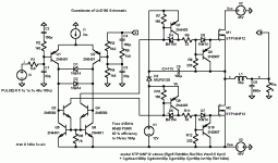
Thanks for the help with the values. I checked some more back threads and found the part number for the output mosfets and the post where Bruno mentioned the values for the feedback resistors. I am attaching an LTspice schematic showing my baseline UcD180 core design guesstimate. With no input it oscillates at about 440kHz with 10ns rise and fall times.
Before commenting on loop design, averaged equivalent circuits, etc., I'd like to get the baseline schematic as correct as possible. Component value checks from UcD180 owners would be most appreciated.")
Once the baseline is finalized I will post its LTspice schematic file and those with the other modifications (dv/dt control, transient damping, leap frog control).
Before commenting on loop design, averaged equivalent circuits, etc., I'd like to get the baseline schematic as correct as possible. Component value checks from UcD180 owners would be most appreciated.
Once the baseline is finalized I will post its LTspice schematic file and those with the other modifications (dv/dt control, transient damping, leap frog control).
Attachments
Hi analogspiceman,
it's a very interesting idea to compare concepts!
However, I'm not sure about UcD180-400 users, because this amp contain two PCB's: mother PCB 65x65mm, and small modulator PCB, which plugged in the mother.The modulator PCB is coated by untransparent compound. So real value of the res&caps seems secret nowadays even..
Edited: Actually, i've feeling that this product already quite protected by the reasonable cost.
Actually, i've feeling that this product already quite protected by the reasonable cost.
That is admittedly true. But the topic of this thread was the comparison of two feedback methods for class-d amps.
For reasons of simplicity I personally prefer topologies that take feedback from a single point.
Regards
Charles
Hi,
I agree with all of the above. However I'm still interested in seeing this continue, I might maybe somehow learn something, and it's a nice change from the "how do I plug it in" threads
So, there's really no need to mimick the actual animal as closely as possible, simply establish your own baseline and all comparisons will be equally valide. It seems like you've got yourself a baseline right there. Nicely done.
Regards
Chris
Chris,
i think, that everyone here awaiting this comparison also, for me would be interesting to build real LF amp(BTW,i'm ready to try) for the sound comparison even. I've just a little doubt about enough equality of the http://www.diyaudio.com/forums/attachment.php?s=&postid=592333&stamp=1110300548 and real product schematics.
i think, that everyone here awaiting this comparison also, for me would be interesting to build real LF amp(BTW,i'm ready to try) for the sound comparison even. I've just a little doubt about enough equality of the http://www.diyaudio.com/forums/attachment.php?s=&postid=592333&stamp=1110300548 and real product schematics.
IVX said:Chris,
i think, that everyone here awaiting this comparison also, for me would be interesting to build real LF amp(BTW,i'm ready to try) for the sound comparison even. I've just a little doubt about enough equality of the http://www.diyaudio.com/forums/attachment.php?s=&postid=592333&stamp=1110300548 and real product schematics.
Hi Ivan and All,
I now have the UcD / LF comparison working, both with ac and transient analyses, the later both with a detailed and an idealized circuit. I don't have time to post the results now (perhaps some tonight, then more on Saturday). Just a little progress report for the forum.
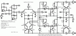
Just to get things started, here is the schematic of a UcD180 power circuit modified to implement leapfrog control (short circuit protection is an inherent, seamless side benefit of leapfrog control). I've also included a very simple, but effective mosfet dv/dt control circuit.
As near as I can tell, LF may be tuned to achieve equal performance to the normal UcD control method, or (unlike UcD) it can be tuned to damp out L-C filter ringing during transient overdrive conditions (where the UcD's feedback loop is momentarily disconnected).
More to follow....
As near as I can tell, LF may be tuned to achieve equal performance to the normal UcD control method, or (unlike UcD) it can be tuned to damp out L-C filter ringing during transient overdrive conditions (where the UcD's feedback loop is momentarily disconnected).
More to follow....
Attachments
IVX said:Hi,
In my experiments UcD show decent clipping behavior.
Why we need the effective mosfet dv/dt control circuit?
Need? That depends. Are the mosfets failing mysteriously? Does the output stage produce excessive EMI?
C5/R14 and C6/R18 limit mosfet turn-on dv/dt by stealing just enough drive current. This has little or no influence on clipping behavior.
Regards -- analog(spiceman)
Hi,
thank you very much for your effort. I am eagerly awaiting continuation. Would you care to show and comment results (not immediately but sometime along your analysis) to what I think is the most acid test for classD: square wave output of unloaded amplifier. I think that LF must excell in that region too.
Best regards,
Jaka Racman
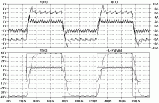
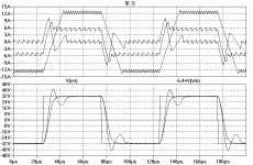
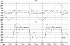
analogspiceman said:Here is a simulation of the LeapFrog controlled UcD power circuit for a 10kHz square wave into an open circuit, a 6 ohm load, and a short circuit. Inductor current is shown in the upper trace.
For comparison, here is a simulation of the unmodified UcD power circuit for a 10kHz square wave into an open circuit, a 6 ohm load, and a short circuit. Inductor current is shown in the upper trace.
Please note that this result is only based on my guess at the UcD180 schematic as shown earlier in this thread.
Attachments
Jaka Racman said:Hi, thank you very much for your effort. I am eagerly awaiting continuation. Would you care to show and comment results (not immediately but sometime along your analysis) to what I think is the most acid test for classD: square wave output of unloaded amplifier. I think that LF must excel in that region too.
Best regards,
Jaka Racman
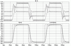
Okay, Jaka, just for you, in order to maximize the cleanliness of the no load response, I've turned down the voltage loop gain a notch or so (I also cut back on the limit level for current a tad, too).
Jaka Racman said:Hi,
you simulate faster than I type.
Thanks,
Jaka Racman
Not really. I'm only using an old 266MHz pentium II (I like it because the kids don't want to use it).
Regards -- analog(spiceman)
Attachments
i just now try simulating too, and i've noted worse THD(.2% vs .02% for UcD at the same comparator based) at the low levels .5-1W(fall I-feedback resolution?). However, for mid power up to around clipping THD almost constant (.1%). Clipping itself is very smooth. THD for 1khz vs 10khz almost equal too (AD826 model used).
Hi Ivan,IVX said:i just now try simulating too, and i've noted worse THD(.2% vs .02% for UcD at the same comparator based) at the low levels .5-1W (fall I-feedback resolution?). However, for mid power up to around clipping THD almost constant (.1%). Clipping itself is very smooth. THD for 1khz vs 10khz almost equal too (AD826 model used).
Thanks for the report. What simulator are you using? (I use LTspice - the best, IMO, and it's free, too!)
I was planning to zip together my simulation files and post them at some point. I have detailed, componnent level models (I've posted gifs of the schematics for those) and idealized models that run faster and are probably better for comparing the basic concepts rather than the strengths of the particular implimentations. The idealized models can also be set up to do ac analyses (closed loop frequency response, loop gain, output impedance) in addition to the usual switching transient type.
Leapfrog depends on sensed current, the quality of which affects the performance (although the outer voltage loop corrects for current sensing anomolies that are within the reach of the voltage loop's lessor loopgain). The cheap and easy current sensing scheme I've shown seems to have lower distortion with higher dc bias. Note that I haven't investigated its sensitivity to component variations or power supply noise, so whether or not it is the best choice remains to be seen.
Also, note that the voltage loop gain of leapfrog can be increased to where it matches UcD (but then the large signal transient response rings just as much). When these gains are the same, THD may be the same (haven't checked yet). Much to do.
Regards -- analogspiceman
Hi analogspiceman, thanks for explaining the leapfrog method well. For example, I was unaware of its usefulness in certain applications. That current sensing circuit is indeed interesting.
I think LTspice is excellent too. It has cool features like the ability to mirror circuit elements ranging from a single component to an entire circuit. Plus, I find its intuitive user interface very helpful.
I think LTspice is excellent too.
It has cool features like the ability to mirror circuit elements ranging from a single component to an entire circuit. Plus, I find its intuitive user interface very helpful.- Status
- This old topic is closed. If you want to reopen this topic, contact a moderator using the "Report Post" button.
- Home
- Amplifiers
- Class D
- Class d control methods: UcD / LF