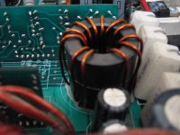
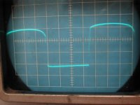
What material to be used for output filter? I built an experimental self-oscilating classD, making the output LC with ferrites (toroidal) it exhibit strange behavior. In small volume, everything is OK, but in medium and high volume, the power amp suddenly sucks big current, the mosfets becomes hot, and the output inductor seems ringing (can be heard, the ringing follows the bass). When checked in osciloscope, in the "on" pulse, there is a blurry area, like comb (in small volume the square is good, without oscilation). Is this because ferrite don't suitable for output LC? What material to be used?
well, for the best quality they usually use coreless coil but they produce strong external EM field like antenna (you'll need some shield). Ferrite has quite low maximum flux density and high non-linearity, so you will need to choose large size cores and take feedback after LC-filter. I tried to use iron powder toroid cores with mu=80...90 but obtained very high core losses at calculated flux of about 0,5 tesla. Main frequency was 120kHz. Then I switched to special combined materials and got better results. The rule to choose material is simple, keep maximum flux below 0,2T; the higher is your carrier frequency, the smaller mu parameter the core must have. For that 120kHz I found good material with mu=36
sorry, I wanted to add some links where you can learn this stuff and choose proper core. I found mine at
http://www.emicore.co.kr/home-e.html
also good information is here:
http://www.micrometals.com/
Alex
http://www.emicore.co.kr/home-e.html
also good information is here:
http://www.micrometals.com/
Alex
I once used a gapped (by the insertion of insulating material) RM ferrite core like Lars does on his one. A gap on the center leg alone would be better though, but not all cores are available with air gap in small quantities:
http://www.lcaudio.com/zp22-1.jpg
I once posted the coarse formulae for calculating air gaps on this forum.
Regards
Charles
http://www.lcaudio.com/zp22-1.jpg
I once posted the coarse formulae for calculating air gaps on this forum.
Regards
Charles
Hi lumanauw,
Your problem is saturation of the core. Ungapped ferrite has high permeability, so magnetic flux density becomes high with small amount of ampere turns. You neeed low permeability core, either gapped ferrite core that is more linear, or distributed gap core like powdered iron or pemalloy. Ungapped ferrite toroid will exhibit high inductance until it comes into saturation when it effectively becomes an air core. So you are facing several thousand times reduction in inductance (difference between initial ferrite permeability and air permeability) or in your case from several miliHenrys to several hundred nanoHenrys. Typical inductance used in classD amps is usually from 10 to 40uH. You were given a lot of good advice from orher posters, so maybe only two things:
Remember that most of the energy in inductor is stored in the air gap, so larger the gap, more energy storage is available (and more problems with fringing flux).
For experimenting, you can dismantle PC power supply. Usually there is one large toroidal powdered core inside, used as secondary coupled inductor with many turns of various diameter magnet wire on it. I have never measured such a core, but my feeling is that it might be used for medium power amplifier if you rewind it and it it has mu less than 100.
Best regards,
Jaka Racman
In addition to the others' ideas, the sound you hear could be an exhibition of magnetorestriction. The physical size of the core actually changes with the magnetic field, causing noise.
A general guideline is that if a DC current is passing through a core, a distributed gap type like iron powder or a gapped ferrite type is required to prevent saturation. Even though the switching frequency may be high in the kilohertz range, the audio component is passing through in a way not totally unlike DC through a power supply filter choke.
A general guideline is that if a DC current is passing through a core, a distributed gap type like iron powder or a gapped ferrite type is required to prevent saturation. Even though the switching frequency may be high in the kilohertz range, the audio component is passing through in a way not totally unlike DC through a power supply filter choke.
Thanks for everybody's input. I got a picture now, the core is saturating. I'll look for other core/material that only gives little uH with many turns.
Is toroidal shape is a problem here or the material itself?
I look at Crown BCA, it uses toroidal shape, but it has many-many windings in it (like 100 or so). In my experimental amp with ferrite toroidal, with 12turns only, I've already got 200uH. So I think the saturation could be the cause.
If the core is saturating in my case, why it makes the mosfets hot and draws so much current? Does "Shoot Through" happens with saturated case, or the hot mosfets are caused by something else? I've burned many-many mosfets. (I use IRF640, is it something wrong with using this?)
I take the feedback after LC filter.
Since I experimented with self-oscilating, it's difficult for me to see what happens in the fault condition. In the fault condition, every track seen in the scopes are mess and moving everytime.
From magnetics, there is a material called "Kool Mu". Is this suitable for this LC filter (because ALME said powdered metal cores are not suitable)
Hello Lumanauw. First, congratulations on choosing to build a class D amp. I have also selected class D for my amplifier project.
I think so too.
Not at all, one main problem, related to the comment by phase_accurate, is obtaining gapped ferrite toroids that are large enough. I would like to see toroids similiar to clamp-on chokes available in much larger sizes.
See Alme's thoughts above about too much magnetization of cores. Fewer turns can tend to subject the core to greater magnetic field strengths, which can either push it into a poor Tesla operating range for its material type and operating frequency, or cause downright saturation.
Jaka explained it well that the choke suddenly loses any ability to cause impedance to the current waveform passing through its windings. Then, essentially, the MOSFETs feel a short circuit to the output filter capacitor. Having a relatively high on-state channel resistance as far as MOSFETs for class D go, the IRF640s quickly overheat because at high frequencies, the filter capacitor has a very low impedance. Yet, at least that channel resistance should tend to reduce high frequency EMI.
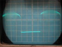
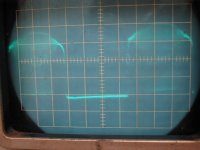
The high currents flowing then cause a lot of induced and conducted spurious signals or hash. It may look like a blur on your scope because it lacks high frequency resolution. But even a 20mhz scope is an immensely useful tool in switching power circuit design. Also, the signals are constantly shifting in phase in relation to the trigger point of the scope trace display.
lumanauw said:Thanks for everybody's input. I got a picture now, the core is saturating. I'll look for other core/material that only gives little uH with many turns.
I think so too.
Is toroidal shape is a problem here or the material itself?
Not at all, one main problem, related to the comment by phase_accurate, is obtaining gapped ferrite toroids that are large enough. I would like to see toroids similiar to clamp-on chokes available in much larger sizes.
I look at Crown BCA, it uses toroidal shape, but it has many-many windings in it (like 100 or so). In my experimental amp with ferrite toroidal, with 12turns only, I've already got 200uH. So I think the saturation could be the cause.
See Alme's thoughts above about too much magnetization of cores. Fewer turns can tend to subject the core to greater magnetic field strengths, which can either push it into a poor Tesla operating range for its material type and operating frequency, or cause downright saturation.
If the core is saturating in my case, why it makes the mosfets hot and draws so much current? Does "Shoot Through" happens with saturated case, or the hot mosfets are caused by something else? I've burned many-many mosfets. (I use IRF640, is it something wrong with using this?)
Jaka explained it well that the choke suddenly loses any ability to cause impedance to the current waveform passing through its windings. Then, essentially, the MOSFETs feel a short circuit to the output filter capacitor. Having a relatively high on-state channel resistance as far as MOSFETs for class D go, the IRF640s quickly overheat because at high frequencies, the filter capacitor has a very low impedance. Yet, at least that channel resistance should tend to reduce high frequency EMI.
I take the feedback after LC filter.
Since I experimented with self-oscilating, it's difficult for me to see what happens in the fault condition. In the fault condition, every track seen in the scopes are mess and moving everytime.
The high currents flowing then cause a lot of induced and conducted spurious signals or hash. It may look like a blur on your scope because it lacks high frequency resolution. But even a 20mhz scope is an immensely useful tool in switching power circuit design. Also, the signals are constantly shifting in phase in relation to the trigger point of the scope trace display.
Hi lumanauw,
you can use KoolMu for cores, in fact I use them too. Just look that you dimension the core properly, with low enough delta B. Remember that you must take two components of signal into consideration when calculating losses. First is inductor ripple due to the switching action of output stage, which you tipically set to 20% of max output current, and then it is maximum amplitude of output current at the highest frequency of interest ( if that is 20kHz or more for audio, then it must be taken into consideration, for subwoofer amp it can be neglected).
On Magnetics web site you will find program for calculating inductors which will give you credible results. You only need to specify DC biased core, where DC current is peak output current of your amplifier.
Best regards,
Jaka Racman
When I learned between pushpull smps and flyback smps, the pushpull type can use smaller dimension ferrite, because the flux swing is in 180deg oposition, nulling each other.
This classD output filter to me is like flyback core. There is no opposite flux that can null it.
Is there any "smart" trick to use pushpull principle in classD output filter, so we can use smaller core size?
I just bought many kind of toroidal cores (powder cores, metal cores, MPP cores, koolmu, I dont know, because the shop don't know what they are). I will try all of them.
What is the indication if one of them is a "success" one? Minimal current draw?
Hi,
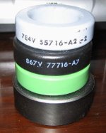
there is no free lunch, you need gapped (low permeability) cores. You can identify CoolMu cores by black color and number 77xxxA7 and MPP cores by grey color and number 55xxxA2. You can get exact data on Magnetics site. Generally inductor can be smaller if you use lower permeability core, but there is limit to it. Magnetics program allows you to dimension inductor according to the max allowed temperature rise. No neeed to blindly try all cores, try rather to learn how to calculate them. This is a rather well understood industry practice, no black art here.
Best regards,
Jaka Racman
lumanauw, if you take feedback after LC-filter, you can try to use cheap type powder cores like computer power supply contains. I measured a couple of such cores and got permeability of about 90. This looks to be some common value, other widely used are 80, 50, 40, 30. I didn't qiute understand in my experiment why such powder core was dissipating over 7 watts at idling, because calculated flux of volt*second operation was about 0,4-0,5T, and they claim maximum flux for iron powder at about 1,4-1,6T. Maybe core losses in powder are highly dependent on frequency. These were the conditions: fsw=120...125kHz, rails +/-65V, core mu=90, toroid 27x15x12x2pcs, winding 20 turns, inductance about 80uH - too high value for full-range amplifier; it was intended for subwoofer though. I must admit that when I turned to special combined material (absolutely the same core size, winding and amplifier), then core heating dropped below 3W.
I think now that you have different cores, first define inductance factor for each of them (AL parameter, that is inductance per 1 turn). if you tell me your frequency, supply rails, load impedance and core size, I can help with choke calculation (experience says that sometimes theory doesn't fit well )
)
I think now that you have different cores, first define inductance factor for each of them (AL parameter, that is inductance per 1 turn). if you tell me your frequency, supply rails, load impedance and core size, I can help with choke calculation (experience says that sometimes theory doesn't fit well
)These are some of the cores I bought. The bottom one is ferrite (with no data), the green one I dont know, the black one is KoolMu and the grey one is MPP. I still got other type, the yellow, the white, the blue cores. But the ones with marking is the black and grey only, others have no data at all.
What does color say about a certain core? Will the color say that "I'm powdered metal core" or "I'm ferrite"? Or color says nothing about a core?
Hi, Jaka,
 They have no marking at all, no data on who is the manufacturer, or even what material it is. Will have to test it in real LC filter.
What does color say about a certain core? Will the color say that "I'm powdered metal core" or "I'm ferrite"? Or color says nothing about a core?
Hi, Jaka,
The problem is, I don't know the properties of the (some) core that I bought.No neeed to blindly try all cores, try rather to learn how to calculate them. This is a rather well understood industry practice, no black art here.
They have no marking at all, no data on who is the manufacturer, or even what material it is. Will have to test it in real LC filter.Attachments
Hi, Subwo1,
Hi, Alme,
What is the usual L value and C value for 1.fullrange classD 2.subwoofer classD? Is there any "good" balance of L value and C value for a certain Xover point? And what is the relation of inductor size and output watt rating from classD audio amp?
There is no fixed frequency. I don't use triangle clocked. I use self-oscilating.
Load impedance, I wanted to be able to drive 2ohm (or 1ohm will be better )
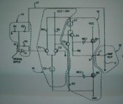
The supply rail is +70/-50V, the topology is like this (you know where it comes from). The opamp is NE5532.
I have a question about this topology. What is the purpose of opamp (receiving input and FB) here. To higher OL gain? What happens if we skip the opamp, and take the input and FB directly to the differential? Will it still works in classD or becomes linear amp? I think if we can get simpler, why go through the hard way. Or we cannot omit opamp in this topology?
I never realize this. Thanks for the input.the audio component is passing through in a way not totally unlike DC through a power supply filter choke.
Hi, Alme,
What is the usual L value and C value for 1.fullrange classD 2.subwoofer classD? Is there any "good" balance of L value and C value for a certain Xover point? And what is the relation of inductor size and output watt rating from classD audio amp?
I cannot measure the inductance per 1turn. Too small for my meter.I think now that you have different cores, first define inductance factor for each of them (AL parameter, that is inductance per 1 turn). if you tell me your frequency, supply rails, load impedance and core size, I can help with choke
There is no fixed frequency. I don't use triangle clocked. I use self-oscilating.
Load impedance, I wanted to be able to drive 2ohm (or 1ohm will be better
)The supply rail is +70/-50V, the topology is like this (you know where it comes from). The opamp is NE5532.
I have a question about this topology. What is the purpose of opamp (receiving input and FB) here. To higher OL gain? What happens if we skip the opamp, and take the input and FB directly to the differential? Will it still works in classD or becomes linear amp? I think if we can get simpler, why go through the hard way. Or we cannot omit opamp in this topology?
Attachments
Hi lumanauw,
both Magnetics cores are good for your application. They both have Mu relative=60 and will have the same inductance with same number of turns. Grey one has lower losses, but is also several times more costly than black one. I would not bother with other cores, MPP is as good as you can get. You can download the catalog here .
Best regards,
Jaka Racman
Hi, Jaka,
Thanks for the info. I haven't experimented yet, I still try looking for other alternative core
I found another interesting candidate. In local electronic store in my town, I found ferrite core, in the form of "Barbel core" (do I say correctly? Like H in circular, if you go to fitness center). It's like the thing for winding wires (imagine you buy magnet wire, it is wounded in this barbel shape core). I try to put many turns and the uH doesn't rise very much. Eventhough it is ferrite, can it be used for output LC, due to its low uH with many turns?
How many uH (+capacitor value) will I need for subwoofer classD and how many uH (+capacitor value) for full range classD?
- Status
- This old topic is closed. If you want to reopen this topic, contact a moderator using the "Report Post" button.
- Home
- Amplifiers
- Class D
- What matrial for output filter?