You're welcome, lumanauw. I believe the core that looks like the dumbbell is called a drum core.
The output filter capacitor often falls in the range of 0.47 to 1 uf. In your scope screen pictures, what is the s/division setting? In other words, what approximately is the period or frequency of oscillation?
The output filter capacitor often falls in the range of 0.47 to 1 uf. In your scope screen pictures, what is the s/division setting? In other words, what approximately is the period or frequency of oscillation?
Hi lumanauw,
the filter inductance in full-range amplifiers I know is from 9uH to 20uH, for subwoofer it is higher and may be over 100uH. In calculation I used the fact that load impedance and inductor together make low-pass filter and its cutoff frequency has to be high enough above the highest signal frequency. I don't know exactly that stuff about LC-filter inside feedback loop, I just learn these topologies now, but I suppose that filter will put additional phase shift to your feedback that has to be compensated somehow. Then I calculated filter capacitor from cutoff frequency of LC-filter (this has to be in between highest signal and carrier frequencies) and also so called characteristic impedance (RO), RO=sqrt(L/C)=has to be close to your load impedance - that is condition of "good balance between L and C" as you say.
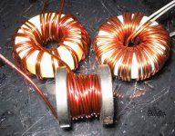
Jaka helped to define your cores, now you can see AL and other parameters in catalog. For the future, to reveal unknown core, you make 10 turns on it, measure L, and to get AL divide that value by 100 (or make 20 turns, measure and divide value by 400, and so forth).
Even if it's self oscillating, there is some 'central' frequency, at least you better know the order of it (80kHz, or 160kHz, etc.) I found your core in catalog and supposing your switching at 200kHz, got 20 turns winding for 0,1tesla voltage operation (this value I think will keep the core just warm) and this corresponds to 30uH inductance - too high for 2Ohm full-range operation - cutoff at 10kHz. You can try to decrease number of turns but check core's temperature at idling switching.
Inductor size also depends on the highest current you want to flow thru it. With 20 turns this core will allow 17A of maximum current at 0,2T current operation, probably slightly low value. Anyway this is 300W RMS at 2 Ohm. For 1Ohm you better find a core with lower mu (because glueing 2 such cores together won't solve this problem). Or maybe I'm mistaken and your feedback will successfully solve core non-linearity distortions at higher flux (they claim maximum of 0,75T for MPP and 1,05T for Kool Mu).
Hope I've been helpful.
Regards,
Alex.
the filter inductance in full-range amplifiers I know is from 9uH to 20uH, for subwoofer it is higher and may be over 100uH. In calculation I used the fact that load impedance and inductor together make low-pass filter and its cutoff frequency has to be high enough above the highest signal frequency. I don't know exactly that stuff about LC-filter inside feedback loop, I just learn these topologies now, but I suppose that filter will put additional phase shift to your feedback that has to be compensated somehow. Then I calculated filter capacitor from cutoff frequency of LC-filter (this has to be in between highest signal and carrier frequencies) and also so called characteristic impedance (RO), RO=sqrt(L/C)=has to be close to your load impedance - that is condition of "good balance between L and C" as you say.
Jaka helped to define your cores, now you can see AL and other parameters in catalog. For the future, to reveal unknown core, you make 10 turns on it, measure L, and to get AL divide that value by 100 (or make 20 turns, measure and divide value by 400, and so forth).
Even if it's self oscillating, there is some 'central' frequency, at least you better know the order of it (80kHz, or 160kHz, etc.) I found your core in catalog and supposing your switching at 200kHz, got 20 turns winding for 0,1tesla voltage operation (this value I think will keep the core just warm) and this corresponds to 30uH inductance - too high for 2Ohm full-range operation - cutoff at 10kHz. You can try to decrease number of turns but check core's temperature at idling switching.
Inductor size also depends on the highest current you want to flow thru it. With 20 turns this core will allow 17A of maximum current at 0,2T current operation, probably slightly low value. Anyway this is 300W RMS at 2 Ohm. For 1Ohm you better find a core with lower mu (because glueing 2 such cores together won't solve this problem). Or maybe I'm mistaken and your feedback will successfully solve core non-linearity distortions at higher flux (they claim maximum of 0,75T for MPP and 1,05T for Kool Mu).
Hope I've been helpful.
Regards,
Alex.
Hi,
not much to add to the excellent advice already given, besides that even at 50A peak (with 20turns) MPP core wil still retain 50% of initial inductance while KoolMu will stay at 45%. One of advantages (or disadvantages) of powdered cores is gradual saturation. This means more headroom for mistakes, but also nonlinear inductance vs bias current. So stay with those cores, with gapped ferrite you would need something even bigger in volume. Plus fringing flux from large airgaps has nasty habit of cooking nearby windings. I doubt you will find drum (or bobbin as it is sometimes called) core sufficiently large for your application.
Second, I think you will find it easier to wind several parallel strands of thinner wire than one thick.
Best regards,
Jaka Racman
Second, I think you will find it easier to wind several parallel strands of thinner wire than one thick.
Not just that, It will also show less losses due to skin-effect !
Regards
Charles
Hi, Subwo1,
Sorry, I dont take note at that time. I will measure it. The signal is 20hz sinewave, but I dont know what frequency the pulses are. The uH at that time is 200uH (with saturating condition)
This is the "Drum" core that I bought yesterday. There are 2 more cores, one is light green and one is yellow. Don't know what they are.
Attachments
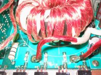
I've used this small+many wires in my SMPS. Like this one, I use 60pcs of 0.3mm wire. (but the insulation is not as good as big wires, you will have to wrap them again with asbestos tube in the ends, otherwise they will scratch each other)
Is this "Skin Effect" attention is a must in output ClassD LC filter too? I usually see factories (Crown BCA and other classD amps) only use 1 big wire, not "litz-wire-kind" bunch.
Is this "Skin Effect" attention is a must in output ClassD LC filter too? I usually see factories (Crown BCA and other classD amps) only use 1 big wire, not "litz-wire-kind" bunch.
Attachments
Hi,
I do not think it is necessary to use litz wire for Class D filter. Usually you have only one layer winding, so it cools down efficiently and besides that high frequency AC ripple current of the switching stage will have relatively low amplitude compared to the full output current. I suggested some (3 or 4) parallell (not twisted) strands because they would cover toroid more evenly and would be easier to wind.
Best regards,
Jaka Racman
lumanauw said:I've used this small+many wires in my SMPS. Like this one, I use 60pcs of 0.3mm wire. (but the insulation is not as good as big wires, you will have to wrap them again with asbestos tube in the ends, otherwise they will scratch each other)
Hi lumanauw,
Hopefully it is really fiberglass tube instead. I think it would be OK to use heat shrink tubing in this case. I just wrap the ends of enameled wire with electrical tape. But, I actually would go with Jaka Racman's suggestion and use something like 4 parallel windings separately wrapped around a core. Because litz wire has such thin insulation, I try to avoid it. Even though these are relatively low voltages present at your amplifier, in some other applications the voltage can arc between windings and short them together.
The "low uH with many turns" cores works. All of them works, none giving the "ringing" like before
Funny thing is, the uH value seems not important, from x1 to x5 like gives no difference?
Since all of them works, how to determine the "best"?
I also have another question. The top gate pulse voltage is like this :
Funny thing is, the uH value seems not important, from x1 to x5 like gives no difference?
Since all of them works, how to determine the "best"?
I also have another question. The top gate pulse voltage is like this :
Attachments
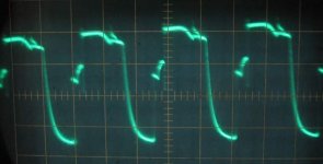
But the lower gate voltage pulse looks like this :
They are different shape, is this OK / normal?
I also experimented with gate resistor value. With 470ohm, when there is no signal the pulses are gone. But with 680ohm, when there is no signal, the pulses are still there.
Which is the right one for self-oscilating classD? It seems with the pulses ON all the time, the current draw seems less (I haven't measure exactly yet)
Hi, Subwo1,
The frequency of the selfoscilating is 29.800hz. I make this for subwoofer, when I finished (and understand all), I dare to make the fullrange self-oscilating.
Hi, Alme,
What is (sqrt)(L/C)? Sorry, I'm not good with English. Is this squareroot of (L/C)?
Attachments
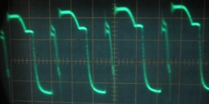
lumanauw said:But the lower gate voltage pulse looks like this :
They are different shape, is this OK / normal?
Hi, Subwo1,
The frequency of the selfoscilating is 29.800hz. I make this for subwoofer, when I finished (and understand all), I dare to make the fullrange self-oscilating.
Thanks for the frequency reading.
I'd say that the gate drive signals are strange mainly because this particular discrete topology is not very well suited for fast MOSFET switching. But if it works for your subwoofer amp, then have fun experimenting with it.
One thing to consider is that the lower MOSFET may get too much voltage applied to its gate if I am seeing the schematic correctly. You may consider using NPN level shifting from the lower rail instead of PNP from the upper, using 15 volt MOSFET drivers. Also consider the IR2011 half-bridge driver IC as your easiest method.Oh your switching frequency is so low, certainly it's only for low frequency amplifier. So how many turns you made for choke? What about core temperature? Try to test it with 2 ohm load.
If the result is good, maybe I'll try Magnetics' cores myself
Yes, sqrt is common abbreviation for square root.
If the result is good, maybe I'll try Magnetics' cores myself
Yes, sqrt is common abbreviation for square root.
Hi,
I would also suggest IR gate drivers instead of discrete ones. Take a look at this post and attached schematics.
You will see UcD like schematic that was posted long before UcD was even known on this forum or patent schematics were made publicly available. If subwo1 is prepared to comment a little further, you will have a very strong foundation to build your design on.
Best regards,
Jaka Racman
Thanks, Jaka Racman. In that diagram, D3 and D4 can be moved to the MOSFET drive output of the IR2110 (IR2113) for fast pull-down of the MOSFET gates and R10 and R11 can be be omitted by simply relying on the MOSFET gate pull-up resistor to slow turn-on times. D8, the 4.7 volt zener diode can be omitted because the current source of the differential input pair does not supply enough current to exceed the current rating of the internal diodes of the 74C14 which shunt over-voltage to the IC's power supply pin. C3 and C4 are internal to the inputs of the IR2110 and can be ignored.
Hi, Jaka,
The design I use is using ordinary discrete totem-pole for driving the mosfets. Is this making the driver signal have strange shape?
Hi, Subwo1,
Where the power for 74HC14 comes from?
Hi, Alme,
Yes, the switching frequency is so low, only 29khz. Because I use 220uF+220uH LC (cutting below 1khz).
Number of turns, yesterday I remember that with 44turns, it gives about 110uH.
Core temperature? I haven't measure it yet. But Jaka seems to advise me to use MPP. I will experimented with all, and if the best is MPP, I will use MPP.
With self-oscilating design, if there is no signal (my CD player is paused), I can get 2 conditions.
1 : with Rg-s 680ohm, I can get the pulses existed everytime, even with no signal input.
2 : with Rg-s 470ohm, I get no pulse if I paused the CD player.
Which is the correct condition for selfoscilating? Does the pulses have tobe there all the time or not?
Hi Lumanauw,
I really enjoy reading about your efforts to learn class-d.
I fully agree with others, you really need to find a better way to drive your mosfets.
An IC driver would be the easiest solution, and would let you drive your mosfets with good authority while you work on perfecting other aspects of your circuit.
However, I find it is nice to know how to properly drive them discretely as well.
It can do the job half decent if you do it right. The following link is a real treasure trove when it comes to learning how mosfets switch.
http://focus.ti.com/lit/ml/slup169/slup169.pdf
This link, will show you a few circuits to show you a proper way of driving them fully discretely, you can pretty well use them as is. The last one shown would be the best for high speed.
http://www.innovatia.com/Design_Center/High-Side Drivers.htm
Just know that it will take alot more effort to get them working well than using a driver IC.
It usually is never shown for logic family IC's or sometimes even with op amps or other components, where it is simply assumed to be there and connected, because there's no way it can work without it.
Yes, typically having zero input signal does not stop the modulator unless other circuitry is setup to make it do that, which isn't wrong. If you don't have that though, it should keep oscillating at a 50% duty cycle for a zero output, until you shut it off or disable it somehow.
Now about all these cores, are you simply buying them locally? Does anyone know of a Digikey like distributor for them? Digikey doesn't seem to have any that I've seen.
Best Regards,
Chris
I really enjoy reading about your efforts to learn class-d.
I fully agree with others, you really need to find a better way to drive your mosfets.
An IC driver would be the easiest solution, and would let you drive your mosfets with good authority while you work on perfecting other aspects of your circuit.
However, I find it is nice to know how to properly drive them discretely as well.
It can do the job half decent if you do it right. The following link is a real treasure trove when it comes to learning how mosfets switch.
http://focus.ti.com/lit/ml/slup169/slup169.pdf
This link, will show you a few circuits to show you a proper way of driving them fully discretely, you can pretty well use them as is. The last one shown would be the best for high speed.
http://www.innovatia.com/Design_Center/High-Side Drivers.htm
Just know that it will take alot more effort to get them working well than using a driver IC.
Where the power for 74HC14 comes from?
It usually is never shown for logic family IC's or sometimes even with op amps or other components, where it is simply assumed to be there and connected, because there's no way it can work without it.
Which is the correct condition for selfoscilating? Does the pulses have tobe there all the time or not?
Yes, typically having zero input signal does not stop the modulator unless other circuitry is setup to make it do that, which isn't wrong. If you don't have that though, it should keep oscillating at a 50% duty cycle for a zero output, until you shut it off or disable it somehow.
Now about all these cores, are you simply buying them locally? Does anyone know of a Digikey like distributor for them? Digikey doesn't seem to have any that I've seen.
Best Regards,
Chris
Hi Chris,
I have gotten cores from CWS Bytemark.
Hi lumanauw,
you could also use the 74C14 chip which should be equivalent to the CD40106. Both require only a few hundred microamps to operate, depending on their output load. So power can be obtained from many sources easily and is referenced to the lower supply rail.
Hi lumanuaw,
I think your gate resistors are to high. Usually for efficient switching value below 20 Ohm is used. However I would like to propose you a design method that will alow you to concentrate your design efforts on one problem at the time.
Generally, self oscillating designs are simpler when everything is finished, but they are pain to debug. So I suggest that you start with PWM function generator at first. If you have a ready made signal generator that's fine, otherwise make some square wave oscillator with 4000 series CMOS gates. Set the frequency to your desired switching frequency (50-100kHz for subwoofer, 350-450Hz for full range amp) and amplitude to 12-15Vpp and duty cycle to 50%. Now try to connect this to one input of your discrete input comparator (differential par) while the other output is connected to gnd. You do not need to connect output filter at this time, and you can connect several ohm non inductive resistor in series with your mosfets to protect them. Now tweak your driver stage untill you get clean switching waveforms on your gates and no shoot through currents in output fets. When this is accomplished, you can remove series resistors from drains and attach output filter. If everything is all right your switching waveforms might look even a little better and power stage should run even a little cooler because of lowered switching losses. Try to run for 15min and evaluate losses in filter inductor. When satisfied, you can attach load and start modulating the duty cycle from 10% to 90%. Observe how amplifier behaves under load.
Once you are satisfied with your power stage, you can change input signal generator from square wave to sine wave and decrease amplitude to 2Vpp or less. If your comparator works well, there should be no difference in switching waveforms of output stage.
You now ready to close output loop. IIRC, UcD has a low gain around switching stage, only around 4, so I would suggest the same. You can have opamp buffer in front of that. Please also remember that series connection of R and C in parallel with feedback resistor is essential part of feedback loop. I think that it was missing from the schematic you posted.
Best regards,
Jaka Racman
This is my first attempt of making classD. I've built analog amp, but this ClassD is quite different, like learning from start again.
There is many-many classD design here. Which one is the closest to UCD?
Hi, Chris,
I think I saw small driver IC here, IR2111 with 8dip only. How many IRF640 in parrarel can this drive? The IC seems small compared to IR2110. And, how to calculate the ability of one IC for driving many mosfets in parrarel?
Yes, I bought the cores here in local store. I don't know if internet shops like Farnell or Arrows also sell them.
Hi, Subwo1,
I like your subwoofer amp. Simple and elegant. For good sounding full range, which one do you suggest?
I have a question. If we put audio signal to a comparator like LM311, will it automaticly perform self-oscilating classD?
Hi, Jaka,
Thanks for the guideline. It will make works in the right track and advoid long time consumption.
The 470R and 680R are not gate resistors (I mistype). They are R from G to S. I dont use gate resistors, just attach totem pole emitors directly to gate.
Who determines the frequency in selfoscilating classD? The LC filter, or something else?
There is many-many classD design here. Which one is the closest to UCD?
Hi, Chris,
I think I saw small driver IC here, IR2111 with 8dip only. How many IRF640 in parrarel can this drive? The IC seems small compared to IR2110. And, how to calculate the ability of one IC for driving many mosfets in parrarel?
Yes, I bought the cores here in local store. I don't know if internet shops like Farnell or Arrows also sell them.
Hi, Subwo1,
I like your subwoofer amp. Simple and elegant. For good sounding full range, which one do you suggest?
I have a question. If we put audio signal to a comparator like LM311, will it automaticly perform self-oscilating classD?
Hi, Jaka,
Thanks for the guideline. It will make works in the right track and advoid long time consumption.
The 470R and 680R are not gate resistors (I mistype). They are R from G to S. I dont use gate resistors, just attach totem pole emitors directly to gate.
I notice in UCD patent, this R-C existed, but why in my prototype (not using it), this prototype can work too?Please also remember that series connection of R and C in parallel with feedback resistor is essential part of feedback loop. I think that it was missing from the schematic you posted.
Who determines the frequency in selfoscilating classD? The LC filter, or something else?
- Status
- This old topic is closed. If you want to reopen this topic, contact a moderator using the "Report Post" button.
- Home
- Amplifiers
- Class D
- What matrial for output filter?