wiring and more
Hi all,
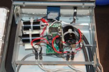
More about wiring!! I just finished modding my SI t-amp as according to panomaniacs and audio1st’s stealth mod, using 2,2uf Solen MKP for input. I also replaced c10 with a 330uf Panasonic FC (I didn’t find anything of greater value that fitted in), and a Panasonic TSHA 10000uF outboard. Question being, as seen from the photo (I hope) the big cap is mounted in parallel with the DC input. Is that correct, or does have to be in series? I also added a Fuse (fast 2A) before the cap, as my external PSU does not have a fuse on the output side. Any problems there?
The modded amp is placed in a case from an external CD-RW. The back trunk is still empty, planning to put a PSU there next.
Anyone looking for air core inductors for the t-amp might find this link useful:
http://www.autocostruire.com/catalog/product_info.php?cPath=32&products_id=256
Thanks from a newbie to all the people here that makes modding so easy and enjoyable.
BTW, I am fascinated by the sound of this modded t-amp.
Hi all,
More about wiring!! I just finished modding my SI t-amp as according to panomaniacs and audio1st’s stealth mod, using 2,2uf Solen MKP for input. I also replaced c10 with a 330uf Panasonic FC (I didn’t find anything of greater value that fitted in), and a Panasonic TSHA 10000uF outboard. Question being, as seen from the photo (I hope) the big cap is mounted in parallel with the DC input. Is that correct, or does have to be in series? I also added a Fuse (fast 2A) before the cap, as my external PSU does not have a fuse on the output side. Any problems there?
The modded amp is placed in a case from an external CD-RW. The back trunk is still empty, planning to put a PSU there next.
Anyone looking for air core inductors for the t-amp might find this link useful:
http://www.autocostruire.com/catalog/product_info.php?cPath=32&products_id=256
Thanks from a newbie to all the people here that makes modding so easy and enjoyable.
BTW, I am fascinated by the sound of this modded t-amp.
Attachments
Phil,
Here's a pic of the Jameco inductors installed on my board.
http://img.photobucket.com/albums/v521/kecline/Sonic T-Amp/Picture193_RS.jpg
The cap is the Panasonic 1500uF (Digi-Key P10254-ND)
-Ken
Here's a pic of the Jameco inductors installed on my board.
http://img.photobucket.com/albums/v521/kecline/Sonic T-Amp/Picture193_RS.jpg
The cap is the Panasonic 1500uF (Digi-Key P10254-ND)
-Ken
Wow. I guess your problem was compounded by the large capacitor you put in there. Those leads do look a bit beefy.
I have 2 SI boards side-by-side, so putting the big toroids in there may be a problem, if they're sticking out like that. Might have to look for smaller ones.
I have 2 SI boards side-by-side, so putting the big toroids in there may be a problem, if they're sticking out like that. Might have to look for smaller ones.
barfind said:I know we discussed cases on about page 9, but wasn't there someone that was making nice looking cases here on the forums. I remember when one of the first mods to the T-Amp was posted there were some pics of a nice case.
Maybe someone will remeber who it was.
Nigel
Do you mean this guy.....
http://mywebpages.comcast.net/ampbox/page2.html


Re: wiring and more
berthej said:Question being, as seen from the photo (I hope) the big cap is mounted in parallel with the DC input. Is that correct
Looks good to me!
I also added a Fuse (fast 2A) before the cap, as my external PSU does not have a fuse on the output side. Any problems there?
Why not! Wont do any harm!
panomaniac said:I looked at the photo again. I'm sure that it is wired wrong. You can see the input wires coming from the RCAs to the caps, then to the pot, then to the board. That puts the pot on the wrong side.
However, I can't tell from the photo (need to look harder) if the stock input caps were removed. If there were not, then no DC offset - but --- no benefit from the new caps.
Pano, you were right. It was wired wrongly. However, because it was not me who modified the t-amp I had no clue about the problem. Friend of mine did not realize that the proper wiring order was of great importance. Good that he did not blow his drivers...
In any way, he did a great job.The only concern I have is that the cap may not be as close to the chip as all you guys recommend. Am I wrong...?
again, thanks to you all. Now I'm starting to wonder how better would charlize or Amp6 sound...
Attachments
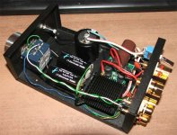
Photo review
Irss,
You have left lots of room for improvement. First you need to insolate the RCA jacks from the chassis if they are not. Then remove the wiring connected to them. Form twisted pairs to connect them directly to the volume control, keeping L/R wires separate. This includes a separate ground connection for each channel. Disconnect the ground jumper on the volume control and run a separate ground for the other channel back to the same ground attachment point on the circuit board. This will improve your high frequency channel separation quite a bit.
If the heat sink is not grounded it should be so it doesn’t radiate noise.
Roger
OK...
I am finally getting close to finishing my t-amp - it took me longer than expected.
Here's what I got so far....
There's some more stuff on it here http://diy-audio.blogspot.com/
-Ken
I am finally getting close to finishing my t-amp - it took me longer than expected.
Here's what I got so far....
An externally hosted image should be here but it was not working when we last tested it.
There's some more stuff on it here http://diy-audio.blogspot.com/
-Ken
Looks well worth the effort, very nice......kec said:
I am finally getting close to finishing my t-amp - it took me longer than expected.

Very nice work, Ken! Classy! We can tell you know what you're doing.
What I really want to know is - where did the knob come from? It's great, haven't seen it before.
BTW, I have a Corian front for one of my amps. But it turned out to be too thick for the volume shaft to go thru and still mount the knob.
What I really want to know is - where did the knob come from? It's great, haven't seen it before.
BTW, I have a Corian front for one of my amps. But it turned out to be too thick for the volume shaft to go thru and still mount the knob.
Thanks guys!
The knob is from apexjr.com - Aluminum Knob (Round) 1 3/8" dia 3/4" tall 1/4" hole w/set screw $4.50ea
http://www.apexjr.com/knobs.htm
I had the same problem too. The Corian is 1/2" and I had to use 1-1/2" forstner bit to mount the Noble pot.
-Ken
What I really want to know is - where did the knob come from? It's great, haven't seen it before.
The knob is from apexjr.com - Aluminum Knob (Round) 1 3/8" dia 3/4" tall 1/4" hole w/set screw $4.50ea
http://www.apexjr.com/knobs.htm
I have a Corian front for one of my amps. But it turned out to be too thick for the volume shaft to go thru and still mount the knob.
I had the same problem too. The Corian is 1/2" and I had to use 1-1/2" forstner bit to mount the Noble pot.
-Ken
Puffin said:What is the largest value cap that could be fitted to replace the power line (330uf 25v) cap. Some suggest 470uf. I have seen 1000uf suggested. I have some 2200uf Nichicons. Woudl these be too big ?
Hi Puffin, this one's a matter of opinion but you need a Low ESR cap here like a panasonic FM/FC etc.
I've tried 680uf and 1000uf in small packages (8mm dia.) and I eventually decided to put two 680's directly onto the pins instead to keep the trace as short as possible. (Vinnie does this on his Clari). Next back from that is a 10,000 uf stiffener very close to the board.
A really good place to put two is on the bottom across the 0.1uf's, see this thread for some good ideas.....
Extreme modding!
Later
Lee
Member
Joined 2003
I replaced the on-board cap with a 680uF, and used a 18,000uF cap off board. The cap is almost as big as the entire pcb, but it was free so I thought I should use it. The amp continues to play for about 3 seconds after the power is cut, and the LED stays on for about a minute after that .
.kec said:[BThe knob is from apexjr.com [/B]
Oh! Well then I have seen it before. I buy from Steve, good guy. The knob looks much better in your photos than on his site. Thanks!
The knob looks much better in your photos than on his site.
Yeah, it looks like a plastic white knob in his picture.
It's solid aluminum with a sandblasted finish. Not sure if it's anodized though. I think it is.
-Ken
- Status
- This old topic is closed. If you want to reopen this topic, contact a moderator using the "Report Post" button.
- Home
- Amplifiers
- Class D
- Sonic Impact 5066 Parts List & Modifications