jkeny said:LostCause,
Can tou give a part number from RS - I'm confused by all the torid specs in this site.
Thanks
John
EDIT**
RS part number:
467-4239
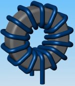
These are the closest I could find, a bit smaller than the ones I have but will actually fit better!
These should require about 14 turns to get to 10uh.
Should be a nice fit with 22SWG wire.
Lee
jkeny said:Thanks LostCause
I just checked them out in local RS suppliers €6.00 for 25 - good deal. Does anybody want some that I will have spare - you pay for postage from Ireland.
John
been there done that!
I think I might have a garage sale (US term) at the end of this, I could mod 20 amps with the stuff I have,maybe I should sell kits (common Capt., you know it makes sense!)......is there ever an end?..........
I have a question for berthej. You paralelled a 10,000uf cap off-board with your modified T-Amp. Does it work and if so what difference do you think it makes. I have various large caps and I am thinking of doing the same. Did you simply connect from the + and - of the underneath of C10 ?
Puffin said:I have a question for berthej. You paralelled a 10,000uf cap off-board with your modified T-Amp. Does it work and if so what difference do you think it makes. I have various large caps and I am thinking of doing the same. Did you simply connect from the + and - of the underneath of C10 ?
Hi Puffin
It works perfectly. For the effect it has, well, I did what you are not supposed to do, but when I had the board out I couldn’t stop myself.

So at the same time I replaced the input caps and the C10, and added the outboard cap. So I am unable to tell you what the difference each of these changes make, but after some hours of break-in the overall effect was incredible, with a much-improved bass response.

Hi berthej, Yes the whole sound is boosted, especially the bass. Its as though it's on steroids !. I left the original 330uf cap in place as I find the more you mess about with the board the more likely it is not to work when you turn it on again ! This has happened to me a lot after carrying out mods. It is mostly the resistor attached to R2pad that comes off. If it pulls the pad off it's curtains. Does anyone know of an alternative place to wire the 22k resistor (Panomaniac's "original" modded T-Amp) if the pad comes off ?
Puffin said:Hi berthej, Yes the whole sound is boosted, especially the bass. Its as though it's on steroids !. I left the original 330uf cap in place as I find the more you mess about with the board the more likely it is not to work when you turn it on again ! This has happened to me a lot after carrying out mods. It is mostly the resistor attached to R2pad that comes off. If it pulls the pad off it's curtains. Does anyone know of an alternative place to wire the 22k resistor (Panomaniac's "original" modded T-Amp) if the pad comes off ?
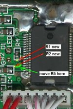
Hi Puffin, this is where I go in with the 'classic' mod.
I use a dremel to open the holes out to .6mm and use it as a through hole connection.
I have also moved the feedback resistor so it sits closer to the chip as shown.
Later
Lee
Attachments
See??? I told you guys that a good stiffener cap for the amp would work wonders. Think of it a "Amplifier Viagra". 
One of my favorite amps ever, the Hiraga Classe-A, used 6x60000uf in the power supply. For a 20 watt amp! I built and used this amp many times, it's a true beauty.
Keeping the power rail strong has a great effect on the over all sound, but the bass seems to benefit most.
In the amps I build now, based on the AMP6, there is 18,000uF before the regulator and 20,000 after it. Even with all that I can still see the voltage fluctuate on the loud passages. Sometimes by 10mV. That's about 63dB down, but might still be heard. But it's miles better than just about any other amp you're likely to hear!
Alternative gnd?
Hi
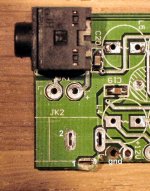
Hope you can help me one this one: when stripping my SI pcb I stripped the DC gnd a little bit too much (nothing but fiber left). Then I removed the plastic DC-input to get access an alternative gnd. But now I don’t know – should I use the (1) or the (2) connection (both normally covered by the DC-input).
Thanks! – and thanks for a great thread.
/Lars
Hi
Hope you can help me one this one: when stripping my SI pcb I stripped the DC gnd a little bit too much (nothing but fiber left). Then I removed the plastic DC-input to get access an alternative gnd. But now I don’t know – should I use the (1) or the (2) connection (both normally covered by the DC-input).
Thanks! – and thanks for a great thread.
/Lars
Attachments
Re: Alternative gnd?
Hi Lars, all depends on what else you are going to do?
If you are replacing C10 then connect both to the leads of the replacement......I have experimented with the ground and it makes no difference unless you are planning to be a little more extreme and put the power caps (C10 replacement) directly to the pins of the chip (then the grounds to their respective pins).
....and that's a LOT of hassle for very little gain!
Lee
larssch said:Hi
Hope you can help me one this one: when stripping my SI pcb I stripped the DC gnd a little bit too much (nothing but fiber left). Then I removed the plastic DC-input to get access an alternative gnd. But now I don’t know – should I use the (1) or the (2) connection (both normally covered by the DC-input).
Thanks! – and thanks for a great thread.
/Lars
Hi Lars, all depends on what else you are going to do?
If you are replacing C10 then connect both to the leads of the replacement......I have experimented with the ground and it makes no difference unless you are planning to be a little more extreme and put the power caps (C10 replacement) directly to the pins of the chip (then the grounds to their respective pins).
....and that's a LOT of hassle for very little gain!
Lee
Re: Alternative gnd?
Hi Lars, if you intend to use the original power switch, or connect a new switch to the red wires, then use point (2) as your ground. If you decide to fit a switch before the board, then you can connect direct to the legs of the C10 Cap, as Lee suggested.(gnd is shaded, pos is nearest chip).
PS you seem to have striped a lot off the board, new inductors and power Cap next?
Barry.
larssch said:– should I use the (1) or the (2) connection (both normally covered by the DC-input).
Hi Lars, if you intend to use the original power switch, or connect a new switch to the red wires, then use point (2) as your ground. If you decide to fit a switch before the board, then you can connect direct to the legs of the C10 Cap, as Lee suggested.(gnd is shaded, pos is nearest chip).
PS you seem to have striped a lot off the board, new inductors and power Cap next?
Barry.
Hi Lee and Barry. Thanks! I’m planning to do the “stealth” modification exactly as shown on Lee’s diagram. I recon I should go for (2) then.
My mod includes T-Induttanze-Litz inductors from Autocostruire, Panasonic power cap, Obbligato 2.2uf caps, Alps pot. Don’t know exactly what to do about the power supply.
Then everything hopefully works I will place it inside a Beomaster 1000 (year 1963) cabinet with a new front. The box is way too big for the amp – but the veneer in old Malaysian teak is just so beautiful!
/Lars
larssch said:Hi Lee and Barry. Thanks! I’m planning to do the “stealth” modification exactly as shown on Lee’s diagram. I recon I should go for (2) then.
My mod includes T-Induttanze-Litz inductors from Autocostruire, Panasonic power cap, Obbligato 2.2uf caps, Alps pot. Don’t know exactly what to do about the power supply.
Then everything hopefully works I will place it inside a Beomaster 1000 (year 1963) cabinet with a new front. The box is way too big for the amp – but the veneer in old Malaysian teak is just so beautiful!
/Lars
Hi Lars, the Stealth mod is Barry's own, he's the smart **** that came up with such a simple but effective ...not to mention easy to read and executable design.
stealth
My pictures on the past posts show the classic input 'optimum'.
and the c10 replacements directly soldered to the pins. By the way, I drill right through the board and connect my power and grounds seperately to the leads...
Happy modding
Lee
larssch said:Then everything hopefully works I will place it inside a Beomaster 1000 (year 1963) cabinet with a new front.
Post photos when you get it done!
BTW, I got your caps off in the mail at long last....
- Status
- This old topic is closed. If you want to reopen this topic, contact a moderator using the "Report Post" button.
- Home
- Amplifiers
- Class D
- Sonic Impact 5066 Parts List & Modifications