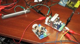
So, here it is, with all the components values.
Features are balanced input, dc, over and under voltage protections, constant delayed turn on/off delay with muting relay, controled by a 4mhz pic microcontroler. All on board supply and control.
I will post the gerbers for the pcb as well.
It sounds good, and works 100% perfect for now, powered with 37v rails.
Balanced input let me bridge two modules together without any additional components outside of the boards, wich i havent try yet. Power output wil be scary i guess.
cheers !!
Attachments
Hi Pat,
Excellent work! I'm new to class D but I must say you have inspired me to give a try. But instead of using a half bridge I'm thinking of using a full bridge. The addition of another gate driver, two mosfets, and some additional components doesn't seem to complicated, but I'm not sure if the integrator feedback circuitry would need to be modified for it to work? Possibly a feedback for the upper and lower mosfets. Any suggestions?
Thanks,
Al
yep, i have tough about that too. I am still fidling the pcb for eventual order from baree bone pcb's.
I think that if you only add the IR part from the hex inverter, but that you invert the signals, i think it may work. Only concern is the added bootstrap cap, it have to be charged before starting the oscillation...
Other than that, i dont think it is necessary to run another feedback path.
I will give it a try in a near future, maybe just a bare bread board test. It could be implemented into my pcb easely, maybe keeping the same size as well...ohhh my...bridged modules already...tons of power !!
Thanks for the quick reply. Keep us all posted on your full bridge, and thanks for sharing your work. I'll keep you posted on how things are go on my end. BTW last year in March i spent a few days in Quebec City. I had a great time, a little cold for me being from Florida but I'd go back in a heart beat. Maybe in the summer this time.
Al
Al
Hi everyones.
I was a bit out of this project, i am mostly a car enthusiast and have way too much projects...
Anyway, i ordered 4 set of PCB of my latest design of this IR amp.
This last one got a microcontroler on each board to monitor the activity, i think i have explained most of this in another thread...
I will let you know how it goes, and will post pictures soon.
thanks
Pat Allen
so far so good...
I fully assembled 2 boards and put them under test...
man these amp sounds soo good !!
Only one problem: the output inductor get soooo hot
yeah, the heat sink is cold, all the rest of the amp barely gets warm even at full power, but the coil, maaannnnnn !!!!
is there a problem, or something that i could do the lower the temp of this coil??
idle curent is very low, sw freq is stable at 400khz.
Inductor spec:
http://www.jwmiller.com/pdf2/2300.pdf
2304-v
its the 2300 series, there is a 2300ht (high temp), i may try it. It will not get colder, but will be able to sustain the high temp...
thanks for any inputs.
Pat Allen
Attachments
Change your filter! At least 47uH with 0.47uF 250V MKT serie should be used...Where are you in Québec? Your filter don't cut as much as you need the carrier....
Thanks
Fred
www.d-amp.com
Thanks
Fred
www.d-amp.com
C'est trops peu 18uh pour shunter une onde carré de 80V p-p...Augment le Q de ton filtre pour avoir une inductance plus grande donc une plus grande resistance a haute frequence, moins de courrant circulant dans ton inductance, moins de perte....Travails-tu présentement? Nous recherchons quelqu'un qui a une expérience avec la class d...
frederic.bourque@d-amp.com
www.d-amp.com
Sorry for all english guy, just fun to talk french of class d!
Fred
frederic.bourque@d-amp.com
www.d-amp.com
Sorry for all english guy, just fun to talk french of class d!
Fred
Salut Fredos !!
merci pour les suggestions.
Comme je disais, je ne me suis pas cassé la tête avec le design, j'ai fait un copy/paste, et j'ai ensuite changé ce qui ne me plaisait pas. IR vend leur demo board avec ces valeurs là.
Pour le reste, je suis en train de mettre ma touche.
J'avais simulé certaines parties du circuit et effectivement, le courant dans la bobine est dans les alentours de 800ma !!!!
J'ai commandé quelques autre bobines dans l'ordre des 22uh à 57uh. Je vais faire des test.
Je crois que IR a mis une 18uh pour accomoder une réponse en fréquence flat avec différentes inpédences...
Pour le travail, merci beaucoup de m'offrir quelque chose, je travaille malheureusement (ou heureusement), je suis concepteur logiciel et matériel. www.astroflex.com
Par curiosité, de quoi s'agit-il ??
Merci !!
Pat
Hi, i sorta resurected this project. I am finishing to build it all and put it in a very nice enclosure. It matches a NAIM preamp that fallen into my hands (old 32.5 ?? with some internal mods) that i will make a whole "unity" system...i guess this will sound awesome.
Both cases, preamp and power amp will be of the same size...
I will post pictures soon.
Both cases, preamp and power amp will be of the same size...
I will post pictures soon.
- Status
- This old topic is closed. If you want to reopen this topic, contact a moderator using the "Report Post" button.
- Home
- Amplifiers
- Class D
- Updated schematic of my class D amp