richie00boy said:
I don't wish things to start getting ugly either, but I did add the caveat "neglecting class-a with large quiescent current requirement" in my first para, which you seem to have neglected")
Yup, I notice now and obviously could have refrained from my post. Reading at the same time as posting is making me sloppy. Sorry.
richie00boy said:
I don't wish things to start getting ugly either, but I did add the caveat "neglecting class-a with large quiescent current requirement" in my first para, which you seem to have neglected
LOL too late I had you quoted!
This is a class d thread though, things still get confusing at times.
classd4sure said:
Power lost as heat in the amp is power that doesn't get to the speaker though. With class d I personally feel it negligible, this isn't the case with other classes though is it?
Why 2X speaker power? When I came up with 800VA for my case, I have two 400W 4Ohm speakers and was going to use one transformer to power them both. You just mean for stereo right? I think you're saying an 800VA would be a approximation in this case and hoping you're not saying i'd need a 1600VA, but it would be nice anyway, if for nothing else, perhaps as a means of theft prevention
UrSv, I personally will be looking forward to and reading your posts.
Damn it got ugly fast in here.
I don't want to get ugly either
2x speaker power is because of this (slightly simplified):
Find the peak voltage required to reach desired power in desired load. This will be the required rail voltage. V = 0.707 * this.
sqrt(800 * 4) = 56.6V
56.6 * 0.707 = 40V
42.2V with diode losses, call it 45V to account for some MOSFET losses as well.
Find the RMS current required to reach desired power in desired load. This will determine wire gauge (and core size, to a degree). I = 1.61 * this.
sqrt(400 / 4) = 10A
10 * 1.61 = 16.1A
Now, multiplying V * I will result in approx 2x the rated audio power.
45 * 16.1 = 724.5VA
Of course, this is for continual sinewaves. If you will be playing music that is not sinewaves and has a high peak to average ratio, then you can undersize the VA somewhat. However, with the trend for modern music to be more and more compressed, I prefer to use the sinewave rating and would not attempt to get 2x 400W of usable, reliable, power out of an 800VA transformer
EDIT: added calculations for UcD400 4 ohm load
classd4sure said:
LOL too late I had you quoted!
This is a class d thread though, things still get confusing at times.
Yes, I did add a little straight after posting for maximal unambiguity. At the time of writing I thought any sensible person would realise that class-a with like 4A quiescent current would have an impact on transformer VA, and this would be factored in
richie00boy said:
I don't want to get ugly either
2x speaker power is because of this (slightly simplified):
Find the peak voltage required to reach desired power in desired load. This will be the required rail voltage. V = 0.707 * this.
Find the RMS current required to reach desired power in desired load. This will determine wire gauge (and core size). I = 1.61 * this.
Now, multiplying V * I will result in approx 2x the rated audio power. Of course, this is for continual sinewaves. If you will be playing music that is not sinewaves and has a high peak to average ratio, then you can undersize the VA a little. However, with the trend for modern music to be more and more compressed, I prefer to use the sinewave rating.
I'd prefer to go with sine rating as well.
Here's an even more simplified version:
2* 400W RMS 4ohm speakers = 800W RMS required=800VA transformer... as VA rating is for continuous output, correct? That is, ignoring amplifier efficiency
classd4sure said:
I'd prefer to go with sine rating as well.
Here's an even more simplified version:
2* 400W RMS 4ohm speakers = 800W RMS required=800VA transformer... as VA rating is for continuous output, correct? That is, ignoring amplifier efficiency
Unfortunately that calculation is meaningless as you have neither magical PSU nor amp from Star Trek
Unfortunately that calculation is meaningless as you have neither magical PSU nor amp from Star Trek
Well, in Star Trek there is no need for calculations anyway.
Just reroute the auxiliary power to Impulse engines, reverse the quantum flow into the main dish and you're all set. Don't forget to recalibrate the power matrix though.
It never should take longer than 50 minutes (length of episode)
Oh, in fact, this solution is omnipotential, it will work for *any* problem in the ST universe!
Hi guys,
This is my first post but I have read all the threads regarding the hypex modules, lc audio modules and their associated power supplies with keen interest.
I feel the need to add my two cents here as you seem to have dismissed what 'djk' is saying...I think he has some smart things to say.
When sourcing transformers for my project...I had a couple of options. The cheap type standard trannies that any old electronics shop stocks or some very high quality custom made types.
The difference...largley 'duty cycle'...oh, and the cost of course. The standard ones are lucky to have a 50% duty cycle....which means under certain conditions and loads they will sag and have troubles. The custom ones I bought are 100% duty cycle....virtually full load all of the time. The difference in size is obvious. My custom type trannies are much LARGER then the standard ones (of the same VA rating btw) you can get from a regular electronics shop. The price of the customs was about 3x that of the standard too.
Re-read his posts....he has some good things to say, duty cycle is a factor worth thinking about
Dave
whams said:Hi guys,
This is my first post but I have read all the threads regarding the hypex modules, lc audio modules and their associated power supplies with keen interest.
I feel the need to add my two cents here as you seem to have dismissed what 'djk' is saying...I think he has some smart things to say.
When sourcing transformers for my project...I had a couple of options. The cheap type standard trannies that any old electronics shop stocks or some very high quality custom made types.
The difference...largley 'duty cycle'...oh, and the cost of course. The standard ones are lucky to have a 50% duty cycle....which means under certain conditions and loads they will sag and have troubles. The custom ones I bought are 100% duty cycle....virtually full load all of the time. The difference in size is obvious. My custom type trannies are much LARGER then the standard ones (of the same VA rating btw) you can get from a regular electronics shop. The price of the customs was about 3x that of the standard too.
Re-read his posts....he has some good things to say, duty cycle is a factor worth thinking about
Dave
You're right, I had misunderstood the term duty cycle as he used it. PNOM = PLOAD (A / B), where a/b is 70% for audio. I automatically and wrongly associated it's use with the output stage duty cycle. I did ask for clarification, though I have no problem admitting I'm wrong.
richie00boy said:
Unfortunately that calculation is meaningless as you have neither magical PSU nor amp from Star Trek
That's obviously not how I originally came up with the number, it's about as much as a calculation as magically doubling required power is.
Find the RMS current required to reach desired power in desired load. This will determine wire gauge (and core size, to a degree). I = 1.61 * this.
Since RMS Power is Vrms X Irms I trust the reason you're multiplying by 1.61 is possibly an attempt to correct what's an assumed rather poor power factor. Would power factor be so poor if caps were kept within reasonable limits?
Not having accounted for it, gets an answer much closer to 800VA, for two speakers that is, 43*20=860VA, more like what I used at the time.
I thought from my post of #23 in this thread you would have got it into your head that I am not simply doubling power arbitrarily. It's not to take account 'in case of' lower loads or anything like that -- it is simply the minimum requirement to drive your desired power into your desired load and no lower, with sinewaves, without burning up.
If you read that post again you will see why the transformer has to have an AC voltage that is 0.707 x DC plus a bit, that I trust is simple and obvious. The reason that DC current is multiplied by 1.61 is that is the current capacity required from the AC side when pulling through a bridge rectifier is increased by this factor. This is simple, fundamental bridge rectifier theory!
Thank you
richie00boy said:I thought from my post of #23 in this thread you would have got it into your head that I am not simply doubling power arbitrarily. It's not to take account 'in case of' lower loads or anything like that -- it is simply the minimum requirement to drive your desired power into your desired load and no lower, with sinewaves, without burning up.
If you read that post again you will see why the transformer has to have an AC voltage that is 0.707 x DC plus a bit, that I trust is simple and obvious. The reason that DC current is multiplied by 1.61 is that is the current capacity required from the AC side when pulling through a bridge rectifier is increased by this factor. This is simple, fundamental bridge rectifier theory!
Thank you
I didn't ask you why you used 45V, if you read my post again, you'll see that simply and obviously. I would say 45V is likely on the high side though, conducting mosfets won't even drop 1 volt.
I'll also point out this is an incorrect way of calculating rails for a UCD which has voltage protection, and for which good design requires one to account for a 10% mains overvoltage condition, as well as the transformer's regulation factor.
Post #23 isn't arbitrary, but a mindless doubling is. You can absorb that much can't you? Maybe if you can't, try comming down from your high horse, it could help.
If it is simple fundamental bridge rectifier theory you're using then you should know it's 1.8. Not a single rectifier version uses 1.61.
You're apparently incapable of an intelligent exchange, perhaps your blood sugar is low? You seem cranky. Go have a biscuit.
Thank you.
Oh come on, let's not let this flare up again
Conducting MOSFETs will drop a little and unless they have a gate driver that can rise above the +ve rail they will drop more than a volt or two. I'm guessing that the UcD will have sufficiently sophisticated drive circuitry to overcome this and thus the bulk of the losses will be through the rectifier diodes. So for a 400W UcD you are looking at a required AC voltage of about 45V. I think we are reasonably in agreement with that.
I agree that for a good design we should take line and transformer regulation into account. However, if we do this it puts up the AC voltage requirement (and hence VA) even more to maintain that 400W output at worst case. And I cannot see what relevance any overvoltage protection an amp may have has in this part of the calculations.
But my whole point was that it appeared to me that I was being accused of mindlessly doubling the speaker power to arrive at the transformer VA. Maybe I was wrong
This is the best bit 1.8 is more than 1.61, which makes the VA add up to even more. That 800VA transformer of yours is now looking rather weedy to drive your 2x 400W amp. This is irrelevant anyway as (and I await your apology ) once you have read a basics text book or searched the net you will see that it is in fact multiply by 1.61 or divide by 0.62 (same result). Remember we are talking about full-wave, bridge rectified AC.
My exchange has been intelligent, I'm the one showing all my working and providing formulas, rather than, umm...
Sound of jammy dodgers packet being opened
classd4sure said:I didn't ask you why you used 45V, if you read my post again, you'll see that simply and obviously. I would say 45V is likely on the high side though, conducting mosfets won't even drop 1 volt.
Conducting MOSFETs will drop a little and unless they have a gate driver that can rise above the +ve rail they will drop more than a volt or two. I'm guessing that the UcD will have sufficiently sophisticated drive circuitry to overcome this and thus the bulk of the losses will be through the rectifier diodes. So for a 400W UcD you are looking at a required AC voltage of about 45V. I think we are reasonably in agreement with that.
classd4sure said:I'll also point out this is an incorrect way of calculating rails for a UCD which has voltage protection, and for which good design requires one to account for a 10% mains overvoltage condition, as well as the transformer's regulation factor.
I agree that for a good design we should take line and transformer regulation into account. However, if we do this it puts up the AC voltage requirement (and hence VA) even more to maintain that 400W output at worst case. And I cannot see what relevance any overvoltage protection an amp may have has in this part of the calculations.
classd4sure said:Post #23 isn't arbitrary, but a mindless doubling is. You can absorb that much can't you? Maybe if you can't, try comming down from your high horse, it could help.
But my whole point was that it appeared to me that I was being accused of mindlessly doubling the speaker power to arrive at the transformer VA. Maybe I was wrong
classd4sure said:If it is simple fundamental bridge rectifier theory you're using then you should know it's 1.8. Not a single rectifier version uses 1.61.
This is the best bit
1.8 is more than 1.61, which makes the VA add up to even more. That 800VA transformer of yours is now looking rather weedy to drive your 2x 400W amp. This is irrelevant anyway as (and I await your apology ) once you have read a basics text book or searched the net you will see that it is in fact multiply by 1.61 or divide by 0.62 (same result). Remember we are talking about full-wave, bridge rectified AC.classd4sure said:You're apparently incapable of an intelligent exchange, perhaps your blood sugar is low? You seem cranky. Go have a biscuit.
Thank you.
My exchange has been intelligent, I'm the one showing all my working and providing formulas, rather than, umm...
Sound of jammy dodgers packet being opened
Oh come on, let's not let this flare up again
Sorry, I've an admittedly weak tolerance for concentrated condescension, like poison it can only be taken in small doses.
Anyway I'm really not here, or trying, to argue, just to learn and help where I can. I do appreciate that your recent post has a much better tone, and so I respond accordingly.
I agree that for a good design we should take line and transformer regulation into account. However, if we do this it puts up the AC voltage requirement (and hence VA) even more to maintain that 400W output at worst case. And I cannot see what relevance any overvoltage protection an amp may have has in this part of the calculations.
Here I fail to understand, you know, thick head and all. The UCD has protection that shuts it down at a certain voltage, used to be 63 volts, now it's higher and a non issue, but this math was done before that, so what the hey. Let's assume a regulation factor of 5%, along with the 10% mains over voltage. We have to allow for a 15% overshoot worst case, without tripping the protection. So realistically we wound up with less voltage, because 56.6 * 1.15 = 65.09 and the amp has cut out 2 volts ago. So then to maintain VA, we'd want more current, but it will never get used because we can't fight ohms law. In reality, what we have isn't exactly a 400W amp. This has been fixed though so it's no longer a problem. That's the relevance to the over voltage protection as I see it. In truth it is no longer relevant with the higher protection level.
But my whole point was that it appeared to me that I was being accused of mindlessly doubling the speaker power to arrive at the transformer VA. Maybe I was wrong
No not at all. I simply wanted to know more about it, which is why I asked originally. I fail to see why you couldn't have explained it without being so condescending. You had a decent answer which left me with another question, apparently you saw that as more accusations, I dont' work that way, I'm fairly straight forward.
This is the best bit I await your apology once you have read a basics text book or searched the net. Remember we are talking about full-wave, bridge rectified AC.
I see more condescension and at this point, the smilie ain't smoothin it over.
http://www.atc-frost.com/products/design/va.htm
http://www.plitron.com/pages/technote.htm
have a scroll down to "Rectifier Circuits"
Apology denied. Besides I don't really care, I was just being combative at this point.
Sound of jammy dodgers packet being opened
I'm glad that amused you, it was meant to.
All the same, it's time I took my leave.
Cheerio, ol chap.
I now see how you were concerned about the overvoltage protection of the UcD400. A very valid concern to those expecting to get 400W out of the amp. I wonder if they have increased the voltage on the amps as well, but's that's not for this thread
I must admit to never having seen the 1.8 factor in over 10 years of electronics, it's always been 1.61. However, those links you posted are valid sources. I can only assume that they are accounting for slightly higher peak currents and/or slightly longer conduction times for the rectifier diodes.
You were doing so well, winning me round, until you dropped that clanger
I think we've covered the bases on this topic anyhow, and anybody should be able to pick up the methodology, reasoning and formulas to design a PSU for a UcD or ZAPpulse amp easily enough from this thread
I must admit to never having seen the 1.8 factor in over 10 years of electronics, it's always been 1.61. However, those links you posted are valid sources. I can only assume that they are accounting for slightly higher peak currents and/or slightly longer conduction times for the rectifier diodes.
classd4sure said:Apology denied. Besides I don't really care, I was just being combative at this point.
You were doing so well, winning me round, until you dropped that clanger
I think we've covered the bases on this topic anyhow, and anybody should be able to pick up the methodology, reasoning and formulas to design a PSU for a UcD or ZAPpulse amp easily enough from this thread
My 45 years of experience, are in garbage can now... terrible feeling!
I can understand why you are discussing that matter so deep, and those things will are confused to me too, as i am completely crazy with things happening here, at my home.
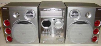
I bougth a very good audio system (sorry, not rich) from Phillips, and its power consumption (written in the back panel) is 125 watts... so i expect to have something around 96 watts power...but as specifications are "manipulated"..... "tricky informs"....i will acept 60 watts of sound....and this is perfect in my mind.... very nice power....because those 45 years, i could realize that normal (not hard to move) speakers, goes to limit movement with 4 or 5 volts.....and the heavier ones need 10 to 15 volts...so.....30 watts is OK!....each channel, perfect!
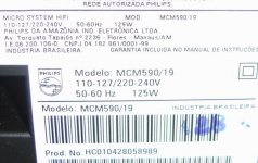
The main problem are specifications...they informed us, power as their top maximum, short time....not even continuous seems to be.... specifications talk in 10 percent distortion....and that distortion is enormous...sounds terrible, it is not more sound, it turns noise!..... and when you go searching, you will find a very small power...i could see 12 watts to a 120 watts amplifier in some Philips Class D chip....and they are making those crazy things with us....mine, with 125 watts consumption, is rated to 200 + 200 watts (they did not tell us what kind of "watts" are those).
This is impossible....125 watts consumption producing more power than consumption....creating energy!
So i connected multimeters....in AC range...good to 60 hertz bass....those instruments can measure with less than 10 percent error, and having some continuous tone, we can avoid problems related to pointer weigth...i tried digital too..... could measure 7 volts over 4 ohms...and, increasing volume, could reach 20 volts, but distortion was a hell, as i use external hi level drive signal, and beeing square waves, measurements loose precision, as turns almost alike continuous.
So, for the good old days ...this amplifier can produce 12 watts each channel, clean watts.... can produce some square crazy wave of much more power.
But this is not what happens hearing....that crazy thing sounds alike 100 watts each channel.... and give a punch in bass enormous...and kicked all my amplifier's s without too much effort, not only in quality of watts produced, as in quantity of watts produced.
So...i cannot understand?....what is going on?
Can i respect those calculations you are discussing to have some idea of the power produced?
I am a hell confused.... those watts i cannot measure with multimeter!!!! HELP!!!
regards,
Carlos
I can understand why you are discussing that matter so deep, and those things will are confused to me too, as i am completely crazy with things happening here, at my home.
I bougth a very good audio system (sorry, not rich) from Phillips, and its power consumption (written in the back panel) is 125 watts... so i expect to have something around 96 watts power...but as specifications are "manipulated"..... "tricky informs"....i will acept 60 watts of sound....and this is perfect in my mind.... very nice power....because those 45 years, i could realize that normal (not hard to move) speakers, goes to limit movement with 4 or 5 volts.....and the heavier ones need 10 to 15 volts...so.....30 watts is OK!....each channel, perfect!
The main problem are specifications...they informed us, power as their top maximum, short time....not even continuous seems to be.... specifications talk in 10 percent distortion....and that distortion is enormous...sounds terrible, it is not more sound, it turns noise!..... and when you go searching, you will find a very small power...i could see 12 watts to a 120 watts amplifier in some Philips Class D chip....and they are making those crazy things with us....mine, with 125 watts consumption, is rated to 200 + 200 watts (they did not tell us what kind of "watts" are those).
This is impossible....125 watts consumption producing more power than consumption....creating energy!
So i connected multimeters....in AC range...good to 60 hertz bass....those instruments can measure with less than 10 percent error, and having some continuous tone, we can avoid problems related to pointer weigth...i tried digital too..... could measure 7 volts over 4 ohms...and, increasing volume, could reach 20 volts, but distortion was a hell, as i use external hi level drive signal, and beeing square waves, measurements loose precision, as turns almost alike continuous.
So, for the good old days ...this amplifier can produce 12 watts each channel, clean watts.... can produce some square crazy wave of much more power.
But this is not what happens hearing....that crazy thing sounds alike 100 watts each channel.... and give a punch in bass enormous...and kicked all my amplifier's s without too much effort, not only in quality of watts produced, as in quantity of watts produced.
So...i cannot understand?....what is going on?
Can i respect those calculations you are discussing to have some idea of the power produced?
I am a hell confused.... those watts i cannot measure with multimeter!!!! HELP!!!
regards,
Carlos
Carlos,
Thank you for your contribution I assume you are using a 'known' same set of speakers for your tests, i.e. the same speakers for each amplifier?
The key thing about rating a transformer is the acceptable tempearture rise for a given power draw.
Your 'boom box' will likely be rated to give out high short term power, but cannot sustain this continuously without overheating the transformer, and the supply begins to collapse after not very long. In contrast, your 'hifi' amplifier will likely have a power supply that cannot match the same short term power as the 'boom box', but it can give out sustained power.
Thank you for your contribution
I assume you are using a 'known' same set of speakers for your tests, i.e. the same speakers for each amplifier?The key thing about rating a transformer is the acceptable tempearture rise for a given power draw.
Your 'boom box' will likely be rated to give out high short term power, but cannot sustain this continuously without overheating the transformer, and the supply begins to collapse after not very long. In contrast, your 'hifi' amplifier will likely have a power supply that cannot match the same short term power as the 'boom box', but it can give out sustained power.
- Status
- This old topic is closed. If you want to reopen this topic, contact a moderator using the "Report Post" button.
- Home
- Amplifiers
- Class D
- Properly sizing transformers for Class D amps