Yes, it is, but I will finally use the 20uH + 440n filter, so sooner or later I have to live with that values. Thanks for the offering, anyway!
I'll keep you posted.
BTW: I know it is very difficult, but what order of magnitude in THD should I expect from the figures I showed? In the order of 0.5-1% or much more? Just to have an idea ;-)
I'll keep you posted.
BTW: I know it is very difficult, but what order of magnitude in THD should I expect from the figures I showed? In the order of 0.5-1% or much more? Just to have an idea ;-)
Well, components changed: Now L=22uH and C=470uF. I hope that helps, this afternoon I will be able to test it and hopefully I can post some images tomorrow.
I am also drawing the sch. in the PC to post it here, as my scanner is broken. Please have some patience. (this way it will be updated with the last changes ;-)
About the distortion, is it possible to know more or less the distortion level I should expect with the waveform I shown?
Thanks!
I am also drawing the sch. in the PC to post it here, as my scanner is broken. Please have some patience. (this way it will be updated with the last changes ;-)
About the distortion, is it possible to know more or less the distortion level I should expect with the waveform I shown?
Thanks!
I still haven't got the time for the test. Arrrggjjj!
Another possibility I have thought of is that the DC cancellation network (a 20k pot with 100k in series with its lets, one connected to +5Vcc and another to -5Vcc, the wiper of the pot joined with 100k to the - input of the error opamp) is causing some mismatch. I will remove that for testing.
Pierre
Well, I tried this morning but, unfortunately I connected something wrong, so I blew up my mosfets (they did a good job protecting my fuses ;-). So it will take me a while to change them and try seriously to see if I get a better waveform with the new values, as by the moment I can only get small periods of time to dedicate to this.
I will be out for a few days, so I expect to have some useful results on tuesday or so.
Thanks for your unvaluable help and merry xmas!
Salut,
Pierre
I will be out for a few days, so I expect to have some useful results on tuesday or so.
Thanks for your unvaluable help and merry xmas!
Salut,
Pierre
Well, back again!
I tried with the corrected filter values and removing the DC offset correction potentiometer. The result is almost the same, the distortion in the waveform is still visible.
Maybe the cause is that there is not enough feedback? How could I correct this, any ideas?
It is strange, as the PWM waveforms look ok and the fidelity was better with fb before filter...mmmm
Thanks and happy new year!
Salut Pierre
There should be enough feedback atr the given dimensioning, although there are possibilities to increase NFB.
Is the amp stable without load ? I yes, then you could do the following test (without load, your PSU will be grateful !):
Feed a very low frequency signal into the amp and watch the signal at the output of the integrator, the output of the comparator, the output of the switching stage and the output filter. Is there anything peculiar happening when the voltage sweeps over approx +- 90 % of the max output voltage ?
Some points one has to watch out for: How is the feedback wired ? Could there be any unwanted pickup from the switching stage.
One has to be aware that there is not only the possibility of unwanted pickup of voltage and magnetic spuriae but also current. It is therefore better to have a differential feedback takeoff.
You could try using an opamp as differential amp for takeing the NFB at the very output. If the situation improves then we have found the problem but still not an optimal solution.
Better would be to make the whole forward path differential, since we want to avoid op-amps in the feedback branch.
Regards
Charles
Thanks, Charles, your willingness to help is always surprising.
I assume you mean using a very low (i.e. visible) sine, for example 1 Hz or less, to see how the PWM moves. And I suppose you request to disconnect load to avoid PSU pumping, right?
My amp doesn't work properly without load, it doesn't oscillate but the output sticks at an arbitrary negative DC level. If you remove the load once it has started, no problem however. And it starts up ok with a load <1.5Kohm or so. Is that ok for the test?
About noise pickup, well, it is possible, but it is strange to me that the distortion is present with any power level, even low ones (where the currents and spikes are quite low to disturb compared to high power levels). It looks the same for 10W and 250W rms . What do you think of this?
The fb path goes by one corner of the board where the output is located by the edge to the middle, so no excessive noise should be picked.
I will observe more deeply with very light loads, let's see how it looks like, and I will tell you.
Thanks!
Salut Pierre
Exactly !
That is a very strange behaviour, I am wondering where this could come from.
With 1.5 k load PSU pumping might not be a problem (depending on the PSU) and you could leave it like that.
I first understood that the distortion was always the same, independant of load impedance. But it seems to be independant of level as well, isn't it ? Do you want to say that even the shape of the signal stays the same independant of its height ? If the latter is the case, how does the input signal look like ?
Regards
Charles
I assume you mean using a very low (i.e. visible) sine, for example 1 Hz or less, to see how the PWM moves. And I suppose you request to disconnect load to avoid PSU pumping, right?
Exactly !
My amp doesn't work properly without load, it doesn't oscillate but the output sticks at an arbitrary negative DC level. If you remove the load once it has started, no problem however.
That is a very strange behaviour, I am wondering where this could come from.
With 1.5 k load PSU pumping might not be a problem (depending on the PSU) and you could leave it like that.
About noise pickup, well, it is possible, but it is strange to me that the distortion is present with any power level, even low ones (where the currents and spikes are quite low to disturb compared to high power levels). It looks the same for 10W and 250W rms . What do you think of this?
I first understood that the distortion was always the same, independant of load impedance. But it seems to be independant of level as well, isn't it ? Do you want to say that even the shape of the signal stays the same independant of its height ? If the latter is the case, how does the input signal look like ?
Regards
Charles
I have been observing a bit more now.
The distortion is a bit higher at high power levels, but the signal is not perfect either at low power levels. I will take some photos and show you. To do that, I will put the scope in averaging mode and the signal measured with a 220ohm + 33nF low pass filter to remove some of the ripple.
This way the waveform should show up as it is, with only the constant distortion (no noise or artifacts due to the switching residue).
About the load, yes, even worse, it doesn't start until the load is about 750 ohms, and even then you need to put some input signal for it to start. mmmm, strange....
Ah, the input signal is quite good, at least it doesn't show the visible distortion. I also suspected of that! ;-)
Best regards.
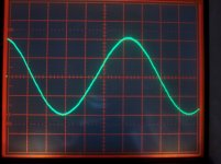
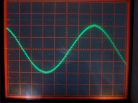
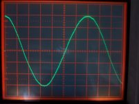
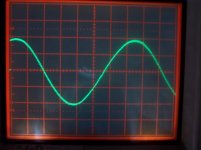
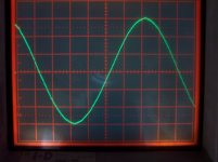
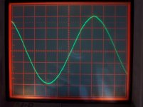
Well, photos taken.
Using average mode of the scope really improves things ;-)
These photos are taken with 256-cycle averaging and a RC filter from the load with a -3dB cutoff freq. of about 32 KHz.
When the signal is small you can still see some ripple, of course.
The input signal is quite good but not perfect, specially in the peaks (it tends to have a little peaky top/bottom)
What do you think of these signals? Do you think that measuring this way is honest? (I think so as you remove noise and carrier and you end only with the amplified signal)
Here you are some photos, I will post the rest in sucesive posts.
Attachments
For the tests shown, I have used a +/-44V supply (no load) with 3x6800uF capacitors per rail, that may have caused an improvement.
About the feedback network: I have reduced the gain, now it has a 47K resistor in parallel with 56pF. The Resistor in the error opamp is 47K also, in parallel with 3k3+330pF. Input resistor is 2K, so gain is about 27dB.
I think that reducing the gain has also improved things, what do you think?
The output filter is 20 uH and 440nF now.
Thanks for your help. I Hope that this discussion is being useful for a lot of people, not only me!
Pierre
- Status
- This old topic is closed. If you want to reopen this topic, contact a moderator using the "Report Post" button.
- Home
- Amplifiers
- Class D
- Help with feedback