looking for the bestest UcD buffer
In fact the UcD offers superior sonic transparency vs ordinary amp , so the reason to have finest buffer is does exist.
Well.. I want to discuss two ways (or more):]
A) Fully differential (THS4131 like) discrete opamp with class A (SE) mosfet output stage- simulations show THD around several micro percents, which have slightly frequency dependance- 10k/1k about 2.
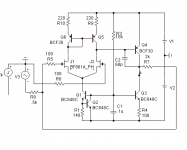
B) i've done simulations for the simplest tube buffer for the UcD- THD about 0.003% (it's for the 100v rails, for the >100v it will much lower) absolutely independent of the frequency.
In fact the UcD offers superior sonic transparency vs ordinary amp , so the reason to have finest buffer is does exist.
Well.. I want to discuss two ways (or more):]
A) Fully differential (THS4131 like) discrete opamp with class A (SE) mosfet output stage- simulations show THD around several micro percents, which have slightly frequency dependance- 10k/1k about 2.
B) i've done simulations for the simplest tube buffer for the UcD- THD about 0.003% (it's for the 100v rails, for the >100v it will much lower) absolutely independent of the frequency.
Attachments
Hi Ivan,
good work! And for two channels already.
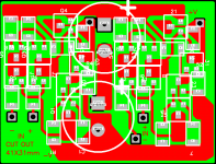
It is not easy to find out, which components are located on top or bottom side. Where are the vias?
If you would shift Q2 a bit to the right, you could place Q1 left besides Q2. C1 and R1 would move a bit up. You don't need the red GND connection between the rail caps really and could place C1 there instead. May be easier for the wiring, to have the outputs not under the rail caps.
These are my thoughts only. Thank you for your work!
If you'd like to produce the PCBs (PCB-pool?), I'd like to buy two of them for sharing costs.
Regards,
Timo
good work! And for two channels already.
It is not easy to find out, which components are located on top or bottom side. Where are the vias?
If you would shift Q2 a bit to the right, you could place Q1 left besides Q2. C1 and R1 would move a bit up. You don't need the red GND connection between the rail caps really and could place C1 there instead. May be easier for the wiring, to have the outputs not under the rail caps.
These are my thoughts only. Thank you for your work!
If you'd like to produce the PCBs (PCB-pool?), I'd like to buy two of them for sharing costs.
Regards,
Timo
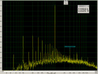
Well, some measurement of the tube buffer is ready. 0.037% THD@1Khz@2Kohm load@~4Vp-p, but voltage gain=6.5 instead 4(simulated), also anodes resistors, which was adjusted for the minimal THD in reality, much less.(about 11Kohm first and 12Kohm second, if both 12Kohm then THD around 0.8%) My measurement and setup aren't precision action generally.. 100hz hum at -60db even, and no any AP just cheap audigy. However one point is clear- the difference of the emission degradation will require regular balancing of the triodes. Quite sad.. i going to knock down my setup.
Ok, Timo,
Good work is never be if just 2 hours spend for it. 10:30am i had wakeup and 12:00am must be starting my day job, BTW today I delayed for 50 minutes. ;-)
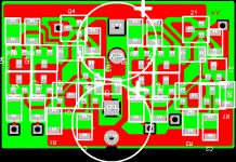
New version PCB done, but one of the decouple cap is out of range, and .33mm lines more now. New dimension are 40x25mm.
Good work is never be if just 2 hours spend for it. 10:30am i had wakeup and 12:00am must be starting my day job, BTW today I delayed for 50 minutes. ;-)
New version PCB done, but one of the decouple cap is out of range, and .33mm lines more now. New dimension are 40x25mm.
Attachments
Great works!
Ideas!
It can be better to design a "mono" PCB to fit directly it on the UcB module.
We remove the op-amp, the 22UF caps and use the free holes and free space to plug the small pcb directly on the UcD module. We use the UcD PSU and try to still use the mute circuit integrated to the UcD module.
With this solution, no cables, better integration and better SN.
stef1777, your idea is cool too much!
Yeah, imagine- JP will make only this version UcD right now, or from the next week ;-) Actually, this is just a virtual project and nothing more, at least before hearing by advanced listeners, i'm not sure that ad8620 or opa627 is worse..
Yeah, imagine- JP will make only this version UcD right now, or from the next week ;-) Actually, this is just a virtual project and nothing more, at least before hearing by advanced listeners, i'm not sure that ad8620 or opa627 is worse..
IVX said:stef1777, your idea is cool too much!
Yeah, imagine- JP will make only this version UcD right now, or from the next week ;-) Actually, this is just a virtual project and nothing more, at least before hearing by advanced listeners, i'm not sure that ad8620 or opa627 is worse..
Don't forget the OPA2134.
Very smooth sound with it.
Hah! Some error in the my tube buffer setup is detected- mosfet current is too small for the 2Kohm load! I'm sorry. Probably this design is not so bad yet, simulation with the same error show 0.025% vs 0.037% achieved by me in saturday! So i hope new measurement will be close to the audigy THD limits! Coming soon..
Well, now is much better. About 3Vp-p output voltage, but load is only ~20Kom, because mosfet current still too small (i'm delayed for my day job for 1.5 hour again .
Edited:
each anodes current are 2.8mA, and unbalance isn't so hard affected now, PS voltage 130V. BTW, this tube i've bought for 0.75 euro, probably it is will be equal cheap sound??? Audigy have own THD=0.002%, so i can't resist to subtract it from 0.0059%..
.Edited:
each anodes current are 2.8mA, and unbalance isn't so hard affected now, PS voltage 130V. BTW, this tube i've bought for 0.75 euro, probably it is will be equal cheap sound??? Audigy have own THD=0.002%, so i can't resist to subtract it from 0.0059%..
Attachments
Thanks guys, however i haven't tried 2Kohm load so far, and probably it's wouldn't be so lucky attempt, there is moot point because mosfet gate charge inherently nonlinear. Seems that not each of the spice model note it? When i'll have a time enough (next weekend if noone have an idea about), 2Kohm load will be checked with irf7103, bs108 and irlml2803, whatever the outcome i'll do it by complicating follower, that isn't preferable yet.
Actually any tube it's a most linear active device around, so our congratulations is rather be adressed to the tube inventors, but not for me.
When i'll have a time enough (next weekend if noone have an idea about), 2Kohm load will be checked with irf7103, bs108 and irlml2803, whatever the outcome i'll do it by complicating follower, that isn't preferable yet. Actually any tube it's a most linear active device around, so our congratulations is rather be adressed to the tube inventors, but not for me.
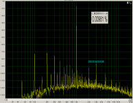
As i'd promised, the new measurement is done. FFT plot captured at next conditions- 6Vp-p@2Kohm load@2.48mA each anode@16mA ir7103 source current. At the 8.2Vp-p output THD about 0.016%, IRLML2803TR (SOT23) allowed better THD performance vs bs108 or ir7103, but too hot, at least in the P2P setup. THD at >1Khz a bit less(-10%-20%). Warm settling time about 2 min, in this time from 0.008% to 0.02% can be seen.. Cathode resistors was 17k one vs 12k other!! BTW, i'd measured only one output of the circuit.. Now we can subtract 0.002%(audigy selfTHD) from the presented THD figures, and conclude that we haven't chance to obtain such figures without fine adjusting of the anode's resistors. 0.05% in the best case and if happy day, on the other hand, who of us equipped even less then i am? After all it must be listened!
edited:
BTW, Koldby has suggested servo circuit to keep close to the zero voltage at outputs.
edited:
BTW, Koldby has suggested servo circuit to keep close to the zero voltage at outputs.
Attachments
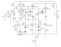
Well, i know that's probably too late to being interesting, but i've done discrete opamp, measured it, and we'll listen it soon. Short form: 140V/Us, 300ns settling, 70db open loop gain with pole about 45khz so THD/Freq plot will be flat up to 45khz also.
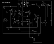
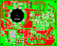
Slowly but smoothly Tube buffer PCB is finished today too. Short form: DC servo (<4hz), delayed outputs connection (relay), onboard 150v (anode U) and +/-15V regulators.
Slowly but smoothly Tube buffer PCB is finished today too. Short form: DC servo (<4hz), delayed outputs connection (relay), onboard 150v (anode U) and +/-15V regulators.
Attachments

- Status
- This old topic is closed. If you want to reopen this topic, contact a moderator using the "Report Post" button.
- Home
- Amplifiers
- Class D
- Looking for the bestest UcD buffer