Everyone's invited in this thread , who wishes to apply some of their valuable knowledge on the class-D amp project which is considered as a revolution in audio amplifier development.
Unlike Class-AB amps this class-D amp must have some advantages over other types, such as
1 Less heat dissipiation
2 High-Fidelity
3 Ease of construction
4 Technological edge.
Now some good assumptions or say Standards[maybe]
1 Carrier must be A near perfect Triangular Wave @250KHz rather than a ramp.Which must be generated by fast opamp.
2 Must avoid use of CMOS IC's.
3 Natural sampling must be done.
4 Quad opamps such as TL074 may be used for avoiding long PCB track connections to prevent stray inductances as well as capacitances.
5 Full Bridge Configuration must be used to eliminate power supply pumping effect.
6 Air-Core inductor filters must be used to avoid saturation effect.
7 Good supply decoupling must be ensured.
8 Dual supply must be used for solidstate grounding w.r.t. positive as well negative bifurcation.
9 PCB track layout must be efficient and proper in R.F. respect.
10 Deadtime must not be greater than 200nS to reduce THD
11 Negative feedback maybe used to reduce THD levels.
12 Noise floor must be isolated by providing seperate grounding for signal path as well as power ground.
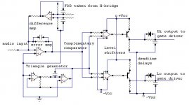
Here is the proposed frontend circuit of Class-D amp
DIYERS are requested to support this projects by constructive criticism and by their valuable suggestions.
Any Queries are most welcomed.
AT last correct me If i were wrong!
Unlike Class-AB amps this class-D amp must have some advantages over other types, such as
1 Less heat dissipiation
2 High-Fidelity
3 Ease of construction
4 Technological edge.
Now some good assumptions or say Standards[maybe]
1 Carrier must be A near perfect Triangular Wave @250KHz rather than a ramp.Which must be generated by fast opamp.
2 Must avoid use of CMOS IC's.
3 Natural sampling must be done.
4 Quad opamps such as TL074 may be used for avoiding long PCB track connections to prevent stray inductances as well as capacitances.
5 Full Bridge Configuration must be used to eliminate power supply pumping effect.
6 Air-Core inductor filters must be used to avoid saturation effect.
7 Good supply decoupling must be ensured.
8 Dual supply must be used for solidstate grounding w.r.t. positive as well negative bifurcation.
9 PCB track layout must be efficient and proper in R.F. respect.
10 Deadtime must not be greater than 200nS to reduce THD
11 Negative feedback maybe used to reduce THD levels.
12 Noise floor must be isolated by providing seperate grounding for signal path as well as power ground.
Here is the proposed frontend circuit of Class-D amp
DIYERS are requested to support this projects by constructive criticism and by their valuable suggestions.
Any Queries are most welcomed.
AT last correct me If i were wrong!
Attachments
Commentable Thoughts
A question arises in my mind about the typical values of level shift resistors.
1 Type of opamp for Triangle generator [100MHz type fast opamp].
2 Can we use quad opamp TL074 for difference amp, error amp, complementary comparators.Will it give better resutls.
3 Howabout using tantalum capacitors for decoupling of supply rails of Gate driver IC IR2110 as well as opamps.
4 Can we fed single triangular wave to multiple comparators in multichannel amp for synchronisation.
5 How much of deadtime will be optimal for avoiding shoot- through in mosfets , while still maintaining sonic linearity i.e. low THD levels.
6 Max level of triangular signal.
7 How much of NFB must be applied.
8 Output filter design such as 2nd order butterwoth.
9 Snubbing Networks as well as Reverse recovery diodes.
EXPERT DIYERS such as
SIR "PHASE_ACCURATE" [CHARLES]
IVX[IVAN]
JAKA RACMAN
SSANMOR[SERGIO]
SUBWO1
Must contribute their valuable suggestions in this Group Project .

If you were going to use a Mosfet driver like IR2110 (this would apply to most drivers anyway), couldn't you eliminate the level shifting by taking the negative rail as the ground and regulating the Centre tap down to the required levels. I assume your initial layout was for a floating supply for the modulation?
I'm not the best on Class D theory but i was under the impression the output inductors were the major factor in determining the damping value, a lower resistance inductor equals a lower damping factor i thought. I'm probably wrong but it was worth a shot.
Also, just out of interest, what is an class D amplifier fabricator doing asking questions on how to make them?
http://pdfserv.maxim-ic.com/en/ds/MAX9700.pdf
Have a look under its spread spectrum feature. I'm not sure whether it will works at lower frequencies and higher power levels but I thought it may be a worth mentioning.
Have a look under its spread spectrum feature. I'm not sure whether it will works at lower frequencies and higher power levels but I thought it may be a worth mentioning.
fr0st said:
Also, just out of interest, what is an class D amplifier fabricator doing asking questions on how to make them?
Mr. Frost We have only manufactured Class-AB N-channel MOSFET/IGBT amplifiers for professional market TILL NOW.
but we are engaged continously in Class-D R&D To start its production for betterment in amplification arena.
Again Thanks For ur comments.
With Regards
Ampman
Commentable Thoughts
Yeah u can be rite , then how we can reference the feedback from the out put of H- Bridge totem pole to the input of difference amp.
With regards
Ampman
fr0st said:If you were going to use a Mosfet driver like IR2110 (this would apply to most drivers anyway), couldn't you eliminate the level shifting by taking the negative rail as the ground and regulating the Centre tap down to the required levels. I assume your initial layout was for a floating supply for the modulation?
Yeah u can be rite , then how we can reference the feedback from the out put of H- Bridge totem pole to the input of difference amp.
With regards
Ampman
Re: Commentable Thoughts
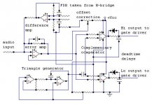
Well , I remember that their is no need to reference the feedback to the center tap of transformer in case of feedback taken from H-bridge and fed to difference amp.
Secondly, only single supply will do the entire job for the amp, Thats why No level shifter, no Dual Supplies.
With Regards
Ampman
amp_man_1 said:
Yeah u can be rite , then how we can reference the feedback from the out put of H- Bridge totem pole to the input of difference amp.
With regards
Ampman
Well , I remember that their is no need to reference the feedback to the center tap of transformer in case of feedback taken from H-bridge and fed to difference amp.
Secondly, only single supply will do the entire job for the amp, Thats why No level shifter, no Dual Supplies.
With Regards
Ampman
Attachments
Opamps are opamps and comparators are comparators. I wouldn't mix them up. I'm almost sure you could use the same opamp for the error amp, difference amp, and triangle generator, but I wouldn't use the same thing for the comparator to make the PWM signal.
With full bridge, the feedback path is necessary, but it is nice for lowering THD.
The level of the triangular wave depends on the input amplitude. General rule of thumb is to have about 80-90% modulation. 100% causes distortion, and its not good to have it too low.
If you're going to do full bridge (I would suggest it), then I would consider a full bridge driver such as the Hip4080 or 4081. This will probably make the output signal more accurate.
Just as a small suggestion, depending on what voltages the rails are, you might want to step down the voltage from the high and low side before the output filters. I don't think the difference amp wants to see a possible +/- 50 volts
Re: Re: Commentable Thoughts
Typo in my last post: The feedback path is NOT necessary in a full bridge design, but it lowers THD
With a bipolar design or a single rail design, you can still take the voltage from between the two mosfets on each side of the bridge and feed it to the difference amp. As mentioned before the voltage needs to be stepped down for higher voltage designs.
amp_man_1 said:
Well , I remember that their is no need to reference the feedback to the center tap of transformer in case of feedback taken from H-bridge and fed to difference amp.
Secondly, only single supply will do the entire job for the amp, Thats why No level shifter, no Dual Supplies.
With Regards
Ampman
Typo in my last post: The feedback path is NOT necessary in a full bridge design, but it lowers THD
With a bipolar design or a single rail design, you can still take the voltage from between the two mosfets on each side of the bridge and feed it to the difference amp. As mentioned before the voltage needs to be stepped down for higher voltage designs.
As far as level shifting and gate drivers go, has any consideration been given to transformer coupling the drive (small ferrite toroids)? I have seen this used in a number of commercial amps, including Peavey's latest line, and would eliminate the need for level shifting, special gate driver ICs with their negative rail referencing, etc. As only around 20turns of wire is required, winding these would be easy and cheap.
Cheers
Cheers
including Peavey's latest line,
Were these of the DPC type ? I assume, since the trafo principle won't work with a real PWM signal. In the DPC case however this transformers always carry a 50% duty-cycle signal.
It would be possible however to make level translation with x-formers with some additional tricks.
Regards
Charles
Commentable Thoughts
To generate a Triangle one must use high speed opamp such as LM6172 100MHZ type.
IS there any other viable substitute other than this is available?
Secondly , The concept of Complementary Comparator is I think is very Good to utilize to generate out of phase PWM signals, instead of using CMOS IC to do that job.
PLZ Comment on it?
Can we rely on the gate capacitance of mosfet to implement Deadtime as The LT schematic [crest audio] illustrates it.
With Compliments
AMPMAN
Ok Guys, Can I say that There is no need of feedback in Full-Bridge topology in case of Class-D amp.
No, you can't say there is *NO* need for feedback in a full bridge design. Is it necessary, no, but again, it will keep the THD down.
For the triangle generator, a 555 timer should work up to about 500kHz.
If you use the IR FETs that are made for Class D amps, you shouldn't have to worry about the internal capacitances.
Hopethat helps
Commentable Thoughts
Acc to my opinion 555 Timer can only generate ramp i.e. Sawtooth wave not the triangular wave which has double sampling resolution than sawtooth.
If I am wrong can u illustrate a circuit for this.
With Compliments
AMPMAN
bknauss said:For the triangle generator, a 555 timer should work up to about 500kHz.
Hopethat helps
Acc to my opinion 555 Timer can only generate ramp i.e. Sawtooth wave not the triangular wave which has double sampling resolution than sawtooth.
If I am wrong can u illustrate a circuit for this.
With Compliments
AMPMAN
Sorry, I was incorrect about the 555 timer. I had a friend that intended on using this, and I thought he said it worked for 400kHz, but the basic triangle wave generator circuit was used.
There is a Maxim signal generator, but it is fairly terrible. I personally saw the waveforms for a triangle wave at 400kHz, and it was very noisy and inaccurate.
There is a Maxim signal generator, but it is fairly terrible. I personally saw the waveforms for a triangle wave at 400kHz, and it was very noisy and inaccurate.
- Status
- This old topic is closed. If you want to reopen this topic, contact a moderator using the "Report Post" button.
- Home
- Amplifiers
- Class D
- Class-D amplifier R&D