I bought a pair of UCD180 HxR version from a guy who never had the time to build an amp. I use a transformer with 2 x 32v windings on each channel, and two 4700microF Rifa phe 169 on each channel. I connected the signalwires to a rca connection, like my drawing tells me. Connected the amp to my preamp...and there was no hiss, no hum, and no sound from my speakers!! Got about +/- 45 volts to each of the modules.
Whats wrong?
Whats wrong?
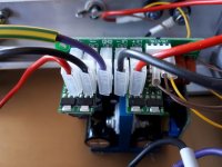
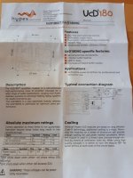
...pin 1 on J4 ? Applying DC voltage to this pin will put the amplifier in standby. Standby logic levels are: high>=3,3 V and low<=0,8 V
Has this changed on the later revisions

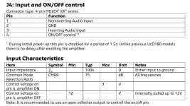
On my old modules (ucd180HG V2) it's pin 4 and it needs to be pulled low for the module to start:
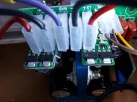
I just measured a few mV on pin 4 on one of my modules with the blue led on.
Attachments
...just checked, enable pin has indeed changed
stenak, please check which version you have - it's printed on the PCB
Enable pin is internal pull-up to 12V, recommended is an open-collector to GND - but I guess a small signal diode to GND will do/ or simply a bit of wire...
stenak, please check which version you have - it's printed on the PCB
Enable pin is internal pull-up to 12V, recommended is an open-collector to GND - but I guess a small signal diode to GND will do/ or simply a bit of wire...
Attachments

Ucd 180"dead"
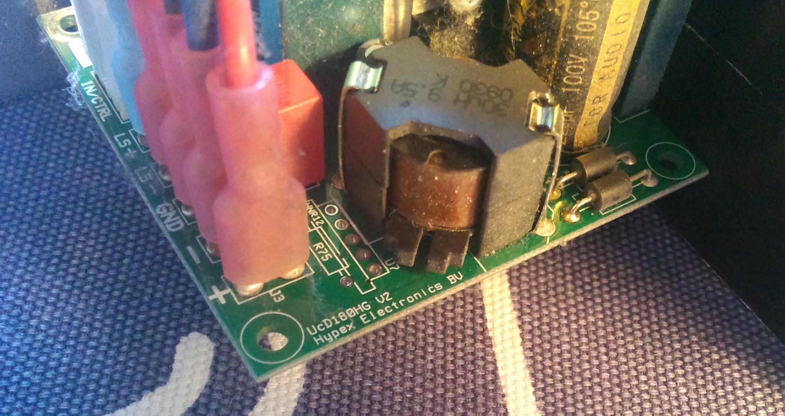
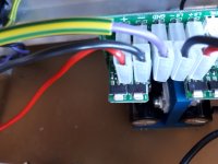
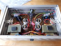
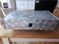
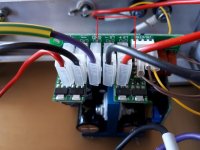
Have not done any checking of voltage etc, but it is +/- 45v on the modules. The red LEDs are shining..Here are some photos. Do not know how you can see what kind of ucd 180 this are?
Have not done any checking of voltage etc, but it is +/- 45v on the modules. The red LEDs are shining..Here are some photos. Do not know how you can see what kind of ucd 180 this are?
Attachments
Nevermind, you have the original 'manual'.
If you look at the 'manual' you see a switch from pin 4 to GND, this turns the amp ON.
In your picture you have nothing connected on pin 4, it's internally connected to 12V (with a resistor) keeping the amp OFF...
At least that's my interpretation....
If you look at the 'manual' you see a switch from pin 4 to GND, this turns the amp ON.
In your picture you have nothing connected on pin 4, it's internally connected to 12V (with a resistor) keeping the amp OFF...
At least that's my interpretation....
Thanks to Kenta 16807 and Davey, and all the others on the forum. It is a great forum for us builders. You find ideas, good help. I think I have to stop building amps, preamps(most tubepre), rebuilding turntables, because I have no more space left... I will find a wire and connect the wire to these connections.
- Status
- This old topic is closed. If you want to reopen this topic, contact a moderator using the "Report Post" button.
- Home
- Amplifiers
- Class D
- Hypex UCD180 HxR. No sound.