Hello,
I have assembled a Hypex kit for 6 channel Linkwitz Studio.
Kit has:
1. DLCP, Input board, Control board
2. 4 Hypex UCD 180 OEM amps
3. 2 Hypex UCD 400 HG amps
4. 1 SMPS400A180 to power the 4 OEM
5. 1 each SMPS400A400 to power each UCD HG Amp.
System works as expected most of the time.
However, occasionally, (more than 3 times a day), the following problem occurs:
1. Pressing volume change buttons (on remote on Control board) does not change the volume physically. The control UI shows volume level changing.
2. At these times, the system uses a default volume.
3. If I try to power off, by remote or Control board, the Control board UI says "Waiting for DLCP" and then does not come out of this state. I have to unplug power.
4. When I resume power, system behaves normally for some time.
Requesting inputs to trouble shoot the problem.
Some notes/observations:
1. Switches on Input board are set correctly. In particular S6 is set to ensure that there is only 1 DLCP in chain.
2. If I disconnect the 2 UCD-HGs from DLCP, by not connecting DLCP J16 to respective SMPS:J5 of each UCD-HG, system seems to be stable. Thus, system is working fine with just the 4 UCD-OEMs being connected. [DLCP J16 is only connected to SMPS's of UCD HGs, not to SMPS of OEM]
3. Also, when only UCD OEMs are connected, ie, without DLCPJ16 being connected to SMPS of UCD HGs, the power off is instantaneous. However, when DLCP J16 is connected to SMPS of UCD HGs, when I hit power off the following sequence happens
4. When the system is not stable, the change w.r.t above scenario is that, after the initial blank screen, the control board does not go blank in step 3 above. None of the Control board keys work. Unplugging input sources makes no difference.
5. Replaced connectors with new ones, and issue persists. Unlikely to be any loose contact anywhere.
6. DLCP and Control board were sent to Hypex for testing - no problems found. Firmware of both were updated to latest by Hypex.
7. Issue is not tied to source of input. Able to see issue when using either optical In or SPDIF In.
8. The mains supply ground is not connected to chassis. DLCP, SMPSes, UCDs all are in contact with chassis. I could see a potential difference between chassis and DLCP J16 Ground on multimeter.
What additional tests should I try, so that the problem can be identified - pls
advise.
I have a suspicion that this has something to do with grounds.
Is there an alternate wiring scheme that is issue proof ?
Many thanks in advance for any help.
Clarification: Power is fed using J4 of DLCP. J16's is NOT used to feed power. Only pin 1, 2 and 5 of J16 are used.
Updates: 25/7/18.
1. Connected protective earth to chassis. (Wasn't connected before).
2. Ensured that all SMPS's metal spacer (connected to chassis) has continuity with chassis. Multimeter indicates continuity between each of the spacers and IEC-in earth pin)
Problem still occurs.
I have assembled a Hypex kit for 6 channel Linkwitz Studio.
Kit has:
1. DLCP, Input board, Control board
2. 4 Hypex UCD 180 OEM amps
3. 2 Hypex UCD 400 HG amps
4. 1 SMPS400A180 to power the 4 OEM
5. 1 each SMPS400A400 to power each UCD HG Amp.
System works as expected most of the time.
However, occasionally, (more than 3 times a day), the following problem occurs:
1. Pressing volume change buttons (on remote on Control board) does not change the volume physically. The control UI shows volume level changing.
2. At these times, the system uses a default volume.
3. If I try to power off, by remote or Control board, the Control board UI says "Waiting for DLCP" and then does not come out of this state. I have to unplug power.
4. When I resume power, system behaves normally for some time.
Requesting inputs to trouble shoot the problem.
Some notes/observations:
1. Switches on Input board are set correctly. In particular S6 is set to ensure that there is only 1 DLCP in chain.
2. If I disconnect the 2 UCD-HGs from DLCP, by not connecting DLCP J16 to respective SMPS:J5 of each UCD-HG, system seems to be stable. Thus, system is working fine with just the 4 UCD-OEMs being connected. [DLCP J16 is only connected to SMPS's of UCD HGs, not to SMPS of OEM]
3. Also, when only UCD OEMs are connected, ie, without DLCPJ16 being connected to SMPS of UCD HGs, the power off is instantaneous. However, when DLCP J16 is connected to SMPS of UCD HGs, when I hit power off the following sequence happens
- the Control screens blanks immediately.
- However, after about 2 seconds it turns back on saying "Waiting for DLCP".
- After about another 2 seconds, the control screen goes blank again, and I can see the the DLCP is turned off.
4. When the system is not stable, the change w.r.t above scenario is that, after the initial blank screen, the control board does not go blank in step 3 above. None of the Control board keys work. Unplugging input sources makes no difference.
5. Replaced connectors with new ones, and issue persists. Unlikely to be any loose contact anywhere.
6. DLCP and Control board were sent to Hypex for testing - no problems found. Firmware of both were updated to latest by Hypex.
7. Issue is not tied to source of input. Able to see issue when using either optical In or SPDIF In.
8. The mains supply ground is not connected to chassis. DLCP, SMPSes, UCDs all are in contact with chassis. I could see a potential difference between chassis and DLCP J16 Ground on multimeter.
What additional tests should I try, so that the problem can be identified - pls
advise.
I have a suspicion that this has something to do with grounds.
Is there an alternate wiring scheme that is issue proof ?
Many thanks in advance for any help.
Clarification: Power is fed using J4 of DLCP. J16's is NOT used to feed power. Only pin 1, 2 and 5 of J16 are used.
Updates: 25/7/18.
1. Connected protective earth to chassis. (Wasn't connected before).
2. Ensured that all SMPS's metal spacer (connected to chassis) has continuity with chassis. Multimeter indicates continuity between each of the spacers and IEC-in earth pin)
Problem still occurs.
Attachments
Last edited:
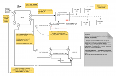
I am using DLCP SMPS to power the DLCP by connecting to SMPS DLCP to J4 of DLCP.
The amp SMPS are NOT connected to DLCP for providing power, but to use the smps standby and amp standby signals available on DLCP J16 so that the DLCP can control the SMPS when it is ready. (My understanding is that amp-standby is used by DLCP to mute the amps, so that is also extracted from DLCPJ16:2 and fed to SMPS400's J5.
In other words, only pin 1,2 and 5 (smps stand by, amp stand by and GND) of J16 are used.
That is how I had wired it up initially. I changed it to this set up in an attempt to fix the instability. Btw, the problem with that set up was that there was a loud pop on power off. Attached is a schematic showing how I had hooked them up initially. The pop up (of UCD HGs) go way with this set up, but pop sound of OEM's remain. Could you please advise me how to avoid pop of the OEM connection? (All signals go to OEM via 20 pin cable from cable DLCP: J1)
Btw, I have noticed that when I connect the power line earth pin to chassis, the instability is MORE frequent. (I can't be 100% sure, of course).
Could some body pls advise what I am expected to see if I measure the potential difference between the following points.
1. Chassis and DLCP J16 Ground pin
2. Chassis and OEM's ground.
3. Chassis and SMPS's J5:5.
Is there any measurement that I can post here, which might help troubleshoot the problem?
Thanks
Attachments
Last edited:
Hi Jalejos, could you please elaborate?
I have not connected the DLCP J16 to SMPS of OEM, because I noticed that amp enable works only for HG, according to data sheet. Is that what you meant?
The amp_enable for the OEMs comes directly from DLCP J1, and not from SMPS, like HGs.
I have not connected the DLCP J16 to SMPS of OEM, because I noticed that amp enable works only for HG, according to data sheet. Is that what you meant?
The amp_enable for the OEMs comes directly from DLCP J1, and not from SMPS, like HGs.
Tried various experiments today.
System is fully stable with only UCD HGs and DLCP ON.
The moment I power the SMPS of UCD OEM, (without giving power to UCD OEMs) system is unstable.
With OEMs also ON,
* with IEC earth pin disconnected, system appears stable with Analogue IN.
* with IEC earth pin disconnected, system stability seems to depend on SPDIF source.
For egs, when I use a device, which when connected, does not light up a tester when the SPDIF cable's end point is touched, system is stable. However When I use device B ( RPI to SPDIF - Allo Digi one), for which the SPDIF cables end connector turns on a tester, the system is unstable - ie, volume keys stop working soon, and power off triggers "waiting for DLCP".
Similarly when I connect my CD player with the SPDIF cable, I can see the tester lighting up on touching the SPDIF end point, and the system is unstable again.
Please avoid sending all the cabling near or over SMPS modules and UCD output coils as from my experience it created kind of interferences from time to time. Proper cabling routing over many swithing-mode modules in one box is as important as layouts of these modules itself...
Hi Jalejos, could you please elaborate?
I have not connected the DLCP J16 to SMPS of OEM, because I noticed that amp enable works only for HG, according to data sheet. Is that what you meant?
The amp_enable for the OEMs comes directly from DLCP J1, and not from SMPS, like HGs.
I am sorry. I misunderstood.
Updates: I think the following could be the root of the issue.
The ground of DLCP is not the same as the ground of rest of the system.
1. The OEMs have their speaker-cold, ground from SMPS at same potential. And OEMs are attached to chassis. So all of these are at same potential. (Chassis not connected to power ground)
2. Similarly the UCD HG's get their ground from their SMPS, and their heat sinks are attached to chassis as well.
3. The DLCP is also attached to chassis via its metal spacers.
So, ground of DLCP should be at same potential as the chassis (or say OEM speaker-cold terminals) right? It isn't.
So, I connected the ground from DLCP:J16 to the J5:ground of all SMPS. I disconnected the smps-stand-by signals, ie DLCP:J16:1 is not connected to anything.
I connect the DLCP:J16:2 (amp_standby) to the UCD-HG SMPS J5.2.
Now when I measure, I can see dlcp:ground and the rest of the system at same ground.
The 2 problems still persist.
If I put the device on stand by, I noticed something strange.
DLCP amp_enable vs dlc:ground shows 4.2 V difference.
DLCP amp_enable vs (say chassis or OEM's ground) starts off by showing 3.2 odd Volts and gradually drops to zero in 10 seconds. Shouldn't it read 4.2 volts as well.
Could someone pls give hints about how to handle ground in the system?
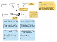
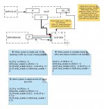
I am able to reproduce the problem with a much simpler set up.
Please see attached schematic. I have also posted various volt-meter readings.
I would also like to re-state the problem more clearly.
1. The system which works perfectly on start up (ie volume control works, stand-by action via remote works as expected) stops listening to volume change command or stand-by command after a few minutes. This problem is limited to an OEM + DLCP environment.
Please see diagrams for a representation of the problem. I am able to reproduce it with 1 OEM alone.
First diagram shows the system with DLCP+DLCP_SMPS isolated from OEM+OEM's SMPS.
You can observe that OEM ground is not zero and has a value. I suspect this is "confusing" DLCP, which is not able to complete a volume control action or a stand-by action and is "waiting for it to complete"
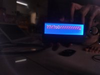
Second diagram shows an attempt to make OEM:ground and DLCP:ground have same 0 value, by connecting them with each other. This attempt also was unsuccessful (ie, problems reported continue to persist). Worse, I see wired things on the Control board UI. See attached pic - control board UI.
Please note that the break-out board between DLCP and OEM does not honur PIN 17 of J1 header. But it does connect the pins 5,6,7,8 of OEM (ie power supply ground) to power supply ground that it gets from SMPS.
Note: I checked the SMPS of OEM as a stand alone device. It seems to work fine. ie, volt readings are stable and positive and negative are steady even after 10 minutes.
Please see attached schematic. I have also posted various volt-meter readings.
I would also like to re-state the problem more clearly.
1. The system which works perfectly on start up (ie volume control works, stand-by action via remote works as expected) stops listening to volume change command or stand-by command after a few minutes. This problem is limited to an OEM + DLCP environment.
Please see diagrams for a representation of the problem. I am able to reproduce it with 1 OEM alone.
First diagram shows the system with DLCP+DLCP_SMPS isolated from OEM+OEM's SMPS.
You can observe that OEM ground is not zero and has a value. I suspect this is "confusing" DLCP, which is not able to complete a volume control action or a stand-by action and is "waiting for it to complete"
Second diagram shows an attempt to make OEM:ground and DLCP:ground have same 0 value, by connecting them with each other. This attempt also was unsuccessful (ie, problems reported continue to persist). Worse, I see wired things on the Control board UI. See attached pic - control board UI.
Please note that the break-out board between DLCP and OEM does not honur PIN 17 of J1 header. But it does connect the pins 5,6,7,8 of OEM (ie power supply ground) to power supply ground that it gets from SMPS.
Note: I checked the SMPS of OEM as a stand alone device. It seems to work fine. ie, volt readings are stable and positive and negative are steady even after 10 minutes.
Attachments
It is likely that the problem lies with the integration of the OEM 180s with the system. The key element in this is the interconnect pcb into which the four 180 modules plug in. All the power, signal and switching is happening via this pcb. We have pretty little details available of this pcb. My assumption is that the trouble could lie in this area. (Do post some pics of the interconnect board so that others could recognize the model and help with their experience.)
Since the DLCP firmware has been updated and checked by Hypex, and as we have two 400HG modules available, IMHO, the way to proceed further is to check out a simple system integration first.
Program the DLCP filters for say, 100 Hz to 10 kHz and feed these to the two 400 modules, connected as per Hypex data sheets. Naturally, here the control signals come from the DLCP, and the DC error signals from the speaker 'hot' point goes to the respective SMPS.
Observer and evaluate this simple system for a while, trying all possible scenarios. Then we will be able to isolate the trouble maker.
Kindly note that switching signals (amp on etc) are all referred to the SMPS zero volt line, and as per Hypex data sheets, the interconnecting cables are enough to establish proper connection between the various modules. The ground connections via the metal stand-offs serve to provide EMI shielding and noise reduction, AFAIK.
It is easy to see that the one non-standard "odd man out" in this setup is the interconnect board for the OEM 180 modules; it could be the ghost in the machine. My suggestion is to get a few adapter pcbs for the 180 modules from Hypex and then try integrating them into the setup later.
Do not give up. Interconnecting a few modules --and that too, proven ones like Hypex-- does not need a PhD in rocket science...now no need to think of the many rockets that ended up in the ocean! All it needs is a systematic approach. Do report your findings with the simple setup.
-UKP
- Status
- This old topic is closed. If you want to reopen this topic, contact a moderator using the "Report Post" button.
- Home
- Amplifiers
- Class D
- Requesting troubleshooting help: Hypex Hybrid DLCP set up