Concept Supply Tracking using Class aP amplification
hellokitty123 and all. I need 2 posts to fully discuss the operation of the attached concept 'supply tracking' schematic.
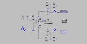
1. U1 is a model power amp using the suggested tracking bipolar PSU [+Vcc/-Vcc]. U1 has an non-inverting AC voltage gain equal to 20. Make believe that it has a complementary-symmetry BJT power output stage.
2. A model signal [Vin] drives the input of U1. The positive part of this AC signal spends time between 0 to t seconds. The negative part of this input AC signal spends its time between t and t1 seconds. Zero crossing of this model AC signal happens at times 0, t, and t1. Zero crossing is/defines a value equal to zero AC and zero DC volts for Vin.
3. U2 and U3 are Class AB power amps using the system's main bipolar PSU [V+/V-]. Each power amp has a DC gain of 20 [like U1] and must be DC-coupled from its non-inverting input to its power output.. This condition is essential for the on-time and in-phase tracking.
4. The non-inverting inputs of U2 and U3 are driven by analog pulses which are derived from and are inherently synchronized with the AC input signal [Vin]. Not shown or discussed yet is the Precision Rectifier which generates the requisite analog pulses.
5. Focus operation on U2. The positive-going analog pulse signal sits atop a fixed [+0.5 VDC]. This +0.5 VDC fixed bias [absent a pulse] is multiplied by the DC voltage gain of U2 to give a [+10 VDC] at its power output which is the idle positive supply voltage for U1 [+Vcc].
6. Focus operation on U3. The negative-going analog pulse signal sits atop a a fixed [-0.5VDC ]. This -0.5VDC fixed bias [absent a pulse] is multiplied by the DC voltage gain of U3 to give a [-10 VDC] at its power output which is the idle negative supply voltage for U1 [-Vcc].
7. Focus operation on the music/AC signal [Vin] during its time interval of 0 to t seconds. Make believe its positive peak value equal to [0.3 Vp]. It follows that the peak value for Vout across the loudspeaker equals [6 Vp] from multiplying 0.3 Vp times 20 which is the AC gain of U1.
7a. Focus operation on U2. A positive analog pulse is derived from [Vin]. It has a peak value equal to [0.3 Vp] and is live in the same time interval of 0 to t of [Vin]. It is presented to the input of U2.
7b. It follows that the peak value of the positive going pulse at the power output of U2 is 6 Vp [0.3 Vp multiplied by 20].
7c.. It follows that the net magnitude of the voltage at the power output of U2 at peak is equal to [10Vdc idle plus 6 Vp] =16 Vp.
7d. This 16 Vp at the power output of U2 is the same as or is the generated tracking +Vcc supply for U1.
7e. The collector-emitter voltage [Vce] across NPN power output of U1 is initially [at idle] held constant at +10 VDC. The rise or increase of voltage at its collector olf 6 Vp [from U2 out] rises or increases at the same instant and magnitude [tracks in real time] the positive-going component of [Vout] at its emitter at the identical value [6 V]. The new dynamic collector voltage of NPN at its peak relative to ground equal 16 Vp. The new Vce of NPN is still held constant at 10 VDC. NPN operates at constant voltage; or call it cascoded!
8. During the time interval of 0 to t for Vout going positive, the negative supply of U1 is held constant at [-10VDC] because the negative component of the Vout signal is not present to enable U3 to supply track.
8b.It follows that Vce for PNP at the power output of U1 increases to an absolute peak value of 16 VDC.
Please do points [7 to 7 e] so as to to grasp negative supply tracking [-Vcc].
To be continued...
hellokitty123 and all. I need 2 posts to fully discuss the operation of the attached concept 'supply tracking' schematic.
1. U1 is a model power amp using the suggested tracking bipolar PSU [+Vcc/-Vcc]. U1 has an non-inverting AC voltage gain equal to 20. Make believe that it has a complementary-symmetry BJT power output stage.
2. A model signal [Vin] drives the input of U1. The positive part of this AC signal spends time between 0 to t seconds. The negative part of this input AC signal spends its time between t and t1 seconds. Zero crossing of this model AC signal happens at times 0, t, and t1. Zero crossing is/defines a value equal to zero AC and zero DC volts for Vin.
3. U2 and U3 are Class AB power amps using the system's main bipolar PSU [V+/V-]. Each power amp has a DC gain of 20 [like U1] and must be DC-coupled from its non-inverting input to its power output.. This condition is essential for the on-time and in-phase tracking.
4. The non-inverting inputs of U2 and U3 are driven by analog pulses which are derived from and are inherently synchronized with the AC input signal [Vin]. Not shown or discussed yet is the Precision Rectifier which generates the requisite analog pulses.
5. Focus operation on U2. The positive-going analog pulse signal sits atop a fixed [+0.5 VDC]. This +0.5 VDC fixed bias [absent a pulse] is multiplied by the DC voltage gain of U2 to give a [+10 VDC] at its power output which is the idle positive supply voltage for U1 [+Vcc].
6. Focus operation on U3. The negative-going analog pulse signal sits atop a a fixed [-0.5VDC ]. This -0.5VDC fixed bias [absent a pulse] is multiplied by the DC voltage gain of U3 to give a [-10 VDC] at its power output which is the idle negative supply voltage for U1 [-Vcc].
7. Focus operation on the music/AC signal [Vin] during its time interval of 0 to t seconds. Make believe its positive peak value equal to [0.3 Vp]. It follows that the peak value for Vout across the loudspeaker equals [6 Vp] from multiplying 0.3 Vp times 20 which is the AC gain of U1.
7a. Focus operation on U2. A positive analog pulse is derived from [Vin]. It has a peak value equal to [0.3 Vp] and is live in the same time interval of 0 to t of [Vin]. It is presented to the input of U2.
7b. It follows that the peak value of the positive going pulse at the power output of U2 is 6 Vp [0.3 Vp multiplied by 20].
7c.. It follows that the net magnitude of the voltage at the power output of U2 at peak is equal to [10Vdc idle plus 6 Vp] =16 Vp.
7d. This 16 Vp at the power output of U2 is the same as or is the generated tracking +Vcc supply for U1.
7e. The collector-emitter voltage [Vce] across NPN power output of U1 is initially [at idle] held constant at +10 VDC. The rise or increase of voltage at its collector olf 6 Vp [from U2 out] rises or increases at the same instant and magnitude [tracks in real time] the positive-going component of [Vout] at its emitter at the identical value [6 V]. The new dynamic collector voltage of NPN at its peak relative to ground equal 16 Vp. The new Vce of NPN is still held constant at 10 VDC. NPN operates at constant voltage; or call it cascoded!
8. During the time interval of 0 to t for Vout going positive, the negative supply of U1 is held constant at [-10VDC] because the negative component of the Vout signal is not present to enable U3 to supply track.
8b.It follows that Vce for PNP at the power output of U1 increases to an absolute peak value of 16 VDC.
Please do points [7 to 7 e] so as to to grasp negative supply tracking [-Vcc].
To be continued...
Attachments
hellokitty123 and all. I need 2 posts to fully discuss the operation of the attached concept 'supply tracking' schematic.
Drivel.
Presumably your second post will correct your Drivel but I will not hold my breath.
What is Drivel?Drivel.
Presumably your second post will correct your Drivel but I will not hold my breath.
What is Drivel?
The Thesaurus defines drivel as silly nonsense. Please continue to breathe. My promised post will follow regardless.
Best
Anton
Not sure I like the idea of having to drive the capacitance of the tracking supply from the input.
Also I would never design U1 to be a complementary output stage. I don't agree with complementary design.
Your requirement for a rectifier seems a bit unoptimal to me. I was thinking full wave replication, after all the tracking supply is basically a voltage cascode which is useful for significant reduction of input capacitance of the stage, not to mention thermal distortion will be improved with a full wave replication I would think.
So the idea is to improve the efficiency of a Class A amp by powering it from two Class AB amps fed by rectifed pulses? Anyone who has looked at modern RF modulation techniques will expect this to be rather difficult to get right; timing is everything.
To me the answer is quite simple: if you want the advantages of Class A then you have to live with the disadvantages of Class A. If you don't wan't to do this then there are other classes to try, principally AB and D.
To me the answer is quite simple: if you want the advantages of Class A then you have to live with the disadvantages of Class A. If you don't wan't to do this then there are other classes to try, principally AB and D.
 @hellokitty123 - it's against the Forum Rules to start multiple threads on the same topic/project, as a result, your threads have been merged.
Maybe better to simply adjust bias by following signal input with opamp.I also want to build a class D tracking power supply to reduce the power dissipation of class A circuits.
- Status
- Not open for further replies.
- Home
- Amplifiers
- Class D
- Using Class D for tracking power supply?