Hello everyone, I'm making my first prototype of IRS2092 coupled to a car switching power supply.
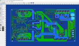
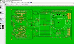
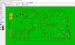
I am recycling the chassis of an old amplifier that could not be repaired, and I made the whole circuit with sprint layout 6.0.
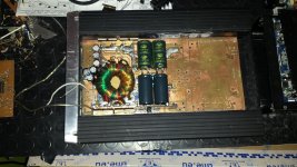
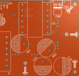
I also publish some photos of the circuit to get you an idea.
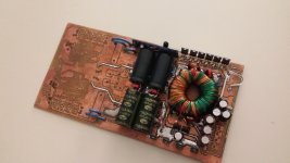
The power supply is regulated, has the rails of +/- 81v, the power supplies for irs2092 are derived from resistor + zener for +/- 5.6v, while the line vcc (12volt) is derived from a secondary winding on the transformer (with referring to the negative rail) filtered, leveled and sent to the irs2092.
I completely finished the power supply, which works great, the problem is that IRS2092 does not really want to collaborate, it does not start, it seems dead, dumb.
I used IRFB4227 as a 4 output MOSFET, and as a driver I used pairs of FZT751TA and NZT560A which should be fine.
I relied on the IRAUDAMP9 project to build the amp, but I can not get it going.
Do you have any ideas?
I checked everything, the power supply works really well, the amplifier does not turn on even if I kick it.
All the tensions are there and they are correct.
At the moment, i've assembled 1 of the 2 channels, but unfortunely i've not photo to show the work, but is very nice, the traces are all shorter than possible to avoid strange phenomena and parasitic capacities on the printed circuit, moreover I have used almost all SMD components.
I checked all the electrical connections, but they are all ok.
I can not understand, I'm starting to hate irs2092.
What do you advise me to do?
I am recycling the chassis of an old amplifier that could not be repaired, and I made the whole circuit with sprint layout 6.0.
I also publish some photos of the circuit to get you an idea.
The power supply is regulated, has the rails of +/- 81v, the power supplies for irs2092 are derived from resistor + zener for +/- 5.6v, while the line vcc (12volt) is derived from a secondary winding on the transformer (with referring to the negative rail) filtered, leveled and sent to the irs2092.
I completely finished the power supply, which works great, the problem is that IRS2092 does not really want to collaborate, it does not start, it seems dead, dumb.
I used IRFB4227 as a 4 output MOSFET, and as a driver I used pairs of FZT751TA and NZT560A which should be fine.
I relied on the IRAUDAMP9 project to build the amp, but I can not get it going.
Do you have any ideas?
I checked everything, the power supply works really well, the amplifier does not turn on even if I kick it.
All the tensions are there and they are correct.
At the moment, i've assembled 1 of the 2 channels, but unfortunely i've not photo to show the work, but is very nice, the traces are all shorter than possible to avoid strange phenomena and parasitic capacities on the printed circuit, moreover I have used almost all SMD components.
I checked all the electrical connections, but they are all ok.
I can not understand, I'm starting to hate irs2092.
What do you advise me to do?
Attachments
Last edited:
Hi there, would be a good idea to attach the schematic. BTW, why you choose such big core for the trafo if you don't fill the window with copper? A smaller trafo(with the same copper cross section) meant less Ls, hence, more output power and efficiency. PCB for a high dI/dt should have a low impedance GND polygon, a solid one, no cuts.
How does the power supply work properly, how can it affect the operation of the amplification section?Hi there, would be a good idea to attach the schematic. BTW, why you choose such big core for the trafo if you don't fill the window with copper? A smaller trafo(with the same copper cross section) meant less Ls, hence, more output power and efficiency. PCB for a high dI/dt should have a low impedance GND polygon, a solid one, no cuts.
This is not about rustling, buzzing, starting noises, the question is that IRS2092 does not start in the slightest, there is not even the typical cyclical click (which would indicate self resetting).
Regarding the amplifier scheme, you can refer to this:
https://media.digikey.com/photos/rdl/IRAUDAMP9_Schematic_4_Full.png
obviously with the output filter.
There are some important news.
I was able to start IRS2092;
Apparently it does not like bus voltage above +/- 80v, so I had to change the feedback circuit to force the power supply to produce +/- 72v, as if by magic, IRS2092 started working so much clean (silent, no clicks, no "tumph", no anomalous heating, everything is perfect).
Now I just have to realize the other channel and the preamp circuit and the phase inversion for one of the 2 channels.
Then I can make some measurements.
How does the power supply work properly, how can it affect the operation of the amplification section?
This is not about rustling, buzzing, starting noises, the question is that IRS2092 does not start in the slightest, there is not even the typical cyclical click (which would indicate self resetting).
Regarding the amplifier scheme, you can refer to this:
https://media.digikey.com/photos/rdl/IRAUDAMP9_Schematic_4_Full.png
obviously with the output filter.
Don't use 2xpair of irfb4227 .and don't use more than 70v supply 63v is best. Irs2092 smd package has some issues dip package is ok for 80v
Don't use 2xpair of irfb4227 .and don't use more than 70v supply 63v is best. Irs2092 smd package has some issues dip package is ok for 80v
I had no problems using 2 pairs of 4227's in a stereo amp I designed.
So long as the gate drivers are powerful enough and gate resistors are low enough it should be fine.
I abandoned the amplifier stage design with IRS2092, unfortunately I continue to fall into the same problem.
It works but at very high volume, irs2092 resets continuously, I tried all sorts of solutions, the result is always the same, the design is very compact, the tracks are all short and the layout is well taken care of, I just can not understand how it can happen.
I'm going to cut the card and save only the power supply, the other half of the card will be made with another type of class D (lm318 + 74hcXX + ir2010).
Unfortunately, after several attempts and design that I have realized, I have always received the same problem, I really got tired of IRS2092.
I had the same problems with irs2092.
1/ Keep tracks as short as possible.
2/ Use decoupling and snubber on output mosfets.
3/ Use transistors or TC4420 gate drivers.
4/ Keep gate resistor low, around 4r7 is best but I have got away with 10 ohms.
5/ The OCP resistors need to be set as high as possible to stop resetting.
6/ Keep smoothing capacitors as close to output mosfets as possible.
7/ If using gate driver transistors they need decoupling with 10uf across their supply.
8/ Deadtime should be max.
Hope this helps.
Note the high side voltage scaler resistor.
An externally hosted image should be here but it was not working when we last tested it.
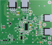
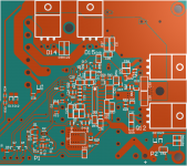
As you noted from the PCB, I used driver transistors to drive irfb4227, and set dead time to the maximum, as suggested in the iraudamp-9 schematic.I had the same problems with irs2092.
1/ Keep tracks as short as possible.
2/ Use decoupling and snubber on output mosfets.
3/ Use transistors or TC4420 gate drivers.
4/ Keep gate resistor low, around 4r7 is best but I have got away with 10 ohms.
5/ The OCP resistors need to be set as high as possible to stop resetting.
6/ Keep smoothing capacitors as close to output mosfets as possible.
7/ If using gate driver transistors they need decoupling with 10uf across their supply.
8/ Deadtime should be max.
Hope this helps.
I made the pcb with the shortest tracks possible, and the layout is really very compact, better than that I could not, I also used 10uf capacitor on the power supply of the drivers, just as shown in the schematic of iraudamp-9, the only thing that I have not done are the points 2, 5, 6, also I do not understand why I set the OCP as high as possible, the schematic iraudamp-9 says falsehood?
Also I used 10omh gate resistors.
I do not understand why.
As you noted from the PCB, I used driver transistors to drive irfb4227, and set dead time to the maximum, as suggested in the iraudamp-9 schematic.
I made the pcb with the shortest tracks possible, and the layout is really very compact, better than that I could not, I also used 10uf capacitor on the power supply of the drivers, just as shown in the schematic of iraudamp-9, the only thing that I have not done are the points 2, 5, 6, also I do not understand why I set the OCP as high as possible, the schematic iraudamp-9 says falsehood?
Also I used 10omh gate resistors.
I do not understand why.
I found I had to set the over current trip level very high to stop resetting.
Note the resistor divider on high side trip level.
From your schematic I realized that you have installed a 10k resistor between PRE-BIASING diode (D3) and HO (I refer to R9), I have never seen in any schematic this resistor, positioning error in the schematic or? I suppose that resistor should go to VB, right?Note the high side voltage scaler resistor.
An externally hosted image should be here but it was not working when we last tested it.
just try this easyyyyy
An externally hosted image should be here but it was not working when we last tested it.
Dinithm, the star is doesn't help, class D as any others hard-switching topology requires a solid GND plane - as you need an air or fishes needs a water.
Attachments
From your schematic I realized that you have installed a 10k resistor between PRE-BIASING diode (D3) and HO (I refer to R9), I have never seen in any schematic this resistor, positioning error in the schematic or? I suppose that resistor should go to VB, right?
The circuit is correct and works with no problems.
I have really designed many circuits using irs2092, both in DIP and SMD.
After spending so much time creating the circuit, making money for the components, struggling to assemble everything by hand, I have always received the same "self resetting" problem.
Each time, the amp sounds very good at low and medium volumes, but as soon as I try to get more power out, irs2092 resets itself;
this time I passed, I used SMD components (to avoid inductive components in the parts), I made a very compact design, but when I saw that there was still self resetting, I demoralized, and I had yet another disappointment .
But I never used 10kohm resistor from prebiasing diode to HO pin. Could it be the cause of my many failures?
no way, it is not principal point at all, just high side driver current consumption less.Could it be the cause of my many failures?
no way, it is not principal point at all, just high side driver current consumption less.
No way, it reduces voltage to high side current sense which will affect reset voltage. Odd my amp with it works ok but his doesn't.
If you set your resistors the same as in the circuit I give it should work.
An externally hosted image should be here but it was not working when we last tested it.
- Status
- This old topic is closed. If you want to reopen this topic, contact a moderator using the "Report Post" button.
- Home
- Amplifiers
- Class D
- IRS2092 diy car Audio stereo amp