What about this? 10 times cheaper than Würth.
LFB095051-000 Laird-Signal Integrity Products | Filters | DigiKey
LFB095051-000 Laird-Signal Integrity Products | Filters | DigiKey
LFB095051-000
http://assets.lairdtech.com/home/brandworld/files/LFB095051-000.pdf
Würth
http://www.farnell.com/datasheets/1919956.pdf
You are right. Great find, I congratulate you. I take note.
http://assets.lairdtech.com/home/brandworld/files/LFB095051-000.pdf
Würth
http://www.farnell.com/datasheets/1919956.pdf
You are right. Great find, I congratulate you. I take note.
From now on it is the one that I will recommend. Many thanks finnsam.
Right now I have warned: Laird-Signal Integrity Products LFB095051-000, ferrite
Right now I have warned: Laird-Signal Integrity Products LFB095051-000, ferrite
Last edited:
This with 7.87mm ID, also cheap
LFB159079-000 Laird-Signal Integrity Products | Filters | DigiKey
LFB159079-000 Laird-Signal Integrity Products | Filters | DigiKey
https://assets.lairdtech.com/home/brandworld/files/Catalog_FERRITE%20CORES%200717.pdf
page 15
FOR ROUND CABLES & WIRING HARNESSES 300 KHZ TO 30 MHZ OPTIMIZE
-> LFB143064-000 70 290 1757
LFB143064-000 Laird-Signal Integrity Products | Filters | DigiKey
https://media.digikey.com/pdf/Data Sheets/Steward PDFs/LFB143064-000.pdf

page 15
FOR ROUND CABLES & WIRING HARNESSES 300 KHZ TO 30 MHZ OPTIMIZE
-> LFB143064-000 70 290 1757
LFB143064-000 Laird-Signal Integrity Products | Filters | DigiKey
https://media.digikey.com/pdf/Data Sheets/Steward PDFs/LFB143064-000.pdf

Würth 150 kHz ferrite


Last edited:
Laird 300 KHZ TO 30 MHZ OPTIMIZED
Laird: FOR ROUND CABLES & WIRING HARNESSES 300 KHZ TO 30 MHZ OPTIMIZED
An externally hosted image should be here but it was not working when we last tested it.
We need to find RF ferrites with similar specifications and ... that can open / close, which is the advantage of the Würth and others.
I guess your radio receives the VHF-Band, i.e. something close to 100MHz. To reduce noise in that band, you require ferrites with a max impedance around 100MHz.
Last edited:
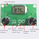
Well, guys I used two ferrites I've bought on the output wires of each channel (RIght and Left) of the amp. I haven't noticed any better quality of the sound. Still the same problem. But, I made something that made the sound almost perfect! I had a wire left on my kitchen and while the radio was playing, I connected the wire to one of the 4 holes that the board has on each side, I touched the antenna on her end of the wire and the sound was much better (almost great)! Is there something wrong with the grounds? I can't understand it. But I still have a little noise on the "not so strong stations".
Attachments
Many years ago a friend told me a phrase that I always remember when I have no explanation: electronics is very mysterious")
Hahaha you're so right my friend! That's why I love Electronics
Many years ago a friend told me a phrase that I always remember when I have no explanation: electronics is very mysterious
Yup.. Them thar RF's are strange critters..
I've used an RC low pass tank circuit with good results. Cut a foil and insert a 60 ohm resistor, bridging the cut, close to the solder pad. Add a 20pF cap after the resistor to ground. (Using surface mount components)
I've done this right at the wire connections on the board. Cut the signal trace right at the solder pad and bridge with the resistor. Install the cap across the wire solder pads, shorting them out with the cap. This provides a low pass circuit that will filter everything above ~130 MHz
I discovered this on a 2.1 amp and the trash from the chip was getting into the sub level control. I installed this filter on the board at the solder pads for the control and the problem went away.
This could be used on the power input also with low current draw demands. 60 ohms isn't going to drop much voltage. Many times that is where the crap is getting into the receiver..
Last edited:
I've used an RC low pass tank circuit with good results. Cut a foil and insert a 60 ohm resistor, bridging the cut, close to the solder pad. Add a 20pF cap after the resistor to ground. (Using surface mount components)
I've done this right at the wire connections on the board. Cut the signal trace right at the solder pad and bridge with the resistor. Install the cap across the wire solder pads, shorting them out with the cap. This provides a low pass circuit that will filter everything above ~130 MHz
I discovered this on a 2.1 amp and the trash from the chip was getting into the sub level control. I installed this filter on the board at the solder pads for the control and the problem went away.
This could be used on the power input also with low current draw demands. 60 ohms isn't going to drop much voltage. Many times that is where the crap is getting into the receiver..
Do you have a schematic of all these connections? It would really help me.
No schematic. All boards are different. The mods I refer to are on/near the outside connections to the board. (plugs/sockets, solder points for external wiring, ect..)
Follow the board traces to the external connections on the board. Cut the trace and jump the cut with a surface mount resistor as close to the edge as possible. Most cases are at the point of which the trace ends at the solder pad for an external connection. The +/- pads are usually close enough to solder a cap across them. Short the pads with a cap..
Soldering a resistor to the cut trace might be difficult for someone who doesn't have lots of experience in soldering. The trace needs scraped to get rid of the insulation so the solder can stick and not destroy the trace. Also, not to scrape any near by traces to avoid bridges. Not a task for a novice..
No schematic. All boards are different. The mods I refer to are on/near the outside connections to the board. (plugs/sockets, solder points for external wiring, ect..)
Follow the board traces to the external connections on the board. Cut the trace and jump the cut with a surface mount resistor as close to the edge as possible. Most cases are at the point of which the trace ends at the solder pad for an external connection. The +/- pads are usually close enough to solder a cap across them. Short the pads with a cap..
Soldering a resistor to the cut trace might be difficult for someone who doesn't have lots of experience in soldering. The trace needs scraped to get rid of the insulation so the solder can stick and not destroy the trace. Also, not to scrape any near by traces to avoid bridges. Not a task for a novice..
Yeap, it sounds like a task for experienced persons. And I'm not.
Is there any filter board on the market that I can use?- Status
- This old topic is closed. If you want to reopen this topic, contact a moderator using the "Report Post" button.
- Home
- Amplifiers
- Class D
- Class D amp + EMI reduction