First of all, let me introduce myself, I realize this might not be the correct place to do so, but anyway.
I started after rave reviews tinkering with these modules, I got my hands on one, and it sounded stunning, so I bought a second one t run them in BTL on my system.
Long story short, no pun intended , I managed to short out the auxiliary power on both of them, I read all possible threads about these modules in this forum, so I know by now where F300 resides, but it is not clear to me where to acquire a replacement fuse, or alternative for it, has anyone any suggestions?
I started after rave reviews tinkering with these modules, I got my hands on one, and it sounded stunning, so I bought a second one t run them in BTL on my system.
Long story short, no pun intended
, I managed to short out the auxiliary power on both of them, I read all possible threads about these modules in this forum, so I know by now where F300 resides, but it is not clear to me where to acquire a replacement fuse, or alternative for it, has anyone any suggestions?Welcome, and good question. IIRC, the datasheet says one of the fuses is not replaceable.
Unlike the main fuse, AFAIK it's soldered in. So, yes, it's a bit more complex but it can be replaced. I would not buy these fuses though, I would use a breadboard and two wires and mount normal fuse fitting on there. If it would happen again, a fuse change is then done within seconds and with minimal tools and effort.
General knowledge about fuses applies:
- Voltage rating
- Current rating
- Time characteristic (fast or slow)
- Package type
The fuse is almost surely SMD. There is a wide selection of SMD fuses in online catalogs of electronic component shops such as Digikey, Mouser, Avnet, Farnell, etc. First locate the correct type of fuse in the catalog of one of these shops. Then find a suitable shop to order, depending on your location.
But: Common wisdom concerning auxiliary PSU for signal circuis dictates that the protection against short circuits in low voltage rails shall be implemented by design, in the form of current limiting and shutdown. For the cases in which the main active current control elements fail there are fusible resistors, often used in primary side.
The reason for these fuses in the low voltage rails in icepower modules remains unclear. There is only one additional case covered by the addition of these fuses: it covers shorts between high voltage rails or speaker outputs to low voltage rails. This addition comes at the expense of paying the learning curve of a SMD fuse replacement for the case of shorts to ground.
125asx2 Auxiliary Aux Power Supply Issues
Hello all,
I'm resurrecting this thread because I am having a similar issue with my 125asx2 auxiliary power supply. Actually, I have 6 of them each in there own enclosure. The amps all work fine with a direct input but I am trying to send the input through an input buffer. This one to be precise.
I had one amp completed and it worked fine for a while. The input buffer was getting power from the auxiliary and everything was working. Then when I went to do the others I started having issues. They all work fine with direct input, but the aux power supply on all of them is bad. Some have absolutely no output and some have very very low output, like less than 1v. The other weird thing is that on all of them the fuse is fine. it's not blown.
Then after all this I went back to the one that was working fine for several days and it stopped working as well with the same issues. Not sure what I could have done wrong. I don't think I crossed any input or anything like that. It seems weird that all 6 would have come to me with bad aux supplies but I also don't know what I could have done wrong.
I might just switch to an external power supply for the input buffer, but I'm hoping to not need to do that because there is no reason not to use the one on the amp.
Any help would be appreciated
I still think this is caused by the fuses. Most often, the AUX supply (if not shorted) goes bad because the AUX power load has a large capacitor over the power lines. The inrush current to this capacitor when switching on, damages and then open the fuse over time.
The solution as recommended by the makers of ICE power is to add a 10 ohms , 2W resistor in series with the AUX power wires to your project. Also be sure not to exceed the rated AUX current (250mA for 125asx2).
The AUX fuses are not the 3 black things near to the connector, but a single red colored rectangle part of the other side of the heat sink, near to the main transformer. It's marked as F300 on the bottom of the PCB.
Fuses are available trough Mouser, Digi-key etc. Mouser order code 530-RST630-BULK
Last edited:
Wow, thanks for the quick reply. I ended up soldering an inline fuse in to bypass the fuse just in case. But I have a very stupid question, actually a few.
Should I be able to read voltage across the aux supply with a volt meter, or is there something about it being unregulated that makes this a bad idea? Because with the fuse in it sometimes will read voltage and then it quickly drops to 0.
Would wiring in a regulator like this be something I need to do?
The PSU you linked is a step-up PSU, to make voltage higher.
As the AUX voltage is already 24-26V (depending on mains voltage), this should be enough for most buffers and pre-amps.
Actually, most buffers needs +12V/-12V or +15V/-15V. Then you probably need something like this:
+15V/-15V 1A AC / DC Regulator Power Dual Supply input 15-18V UN-Assembled Kit | eBay
Don't forget to add the 10 ohm resistors. One in the + and one in the - of the AUX power lines to your buffer.
The AUX power can be measured with a volt meter, just be sure to measure at the connector, not near the fuse.
The PSU you linked is a step-up PSU, to make voltage higher.
Input voltage: 2V-24V
Output voltage: 5V-28V
It can do both.
I've used a very similar one and would not recommend it for audio purposes because of the high ripple and noise it produces. It was so bad I didn't even bother to try to add Cs and chokes.
Actually, most buffers needs +12V/-12V or +15V/-15V. Then you probably need something like this:
+15V/-15V 1A AC / DC Regulator Power Dual Supply input 15-18V UN-Assembled Kit | eBay
That will work just fine. But there's no need to spend more and have the effort in soldering it yourself if you can get cheaper already assembled.
That will work just fine. But there's no need to spend more and have the effort in soldering it yourself if you can get cheaper already assembled.
I kind of like the kits. They let me practice my soldering skills and I'd rather do that on something easy and predictable like this. ;-)
I got this working for now, but I will definitely keep these in mind for any upcoming projects.
Very stupid mistake
I made a very stupid mistake and maybe you could help me out.
I shortened the auxiliary power and in search for the aux fuse I used this thread. So far so good. But when I the fuse I noticed that this fuse was bypassed (by the previous owner...).
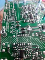
So I searched for broken parts on the board... I found one part broken (in the middle of the picture) but I can't figure out it's part number or value. Hate to admit it but I even don't know if this is the only part broken...
The amplifier bit does work fortunately.....
I hope you can help me...
R.
I made a very stupid mistake and maybe you could help me out.
I shortened the auxiliary power and in search for the aux fuse I used this thread. So far so good. But when I the fuse I noticed that this fuse was bypassed (by the previous owner...).
So I searched for broken parts on the board... I found one part broken (in the middle of the picture) but I can't figure out it's part number or value. Hate to admit it but I even don't know if this is the only part broken...
The amplifier bit does work fortunately.....
I hope you can help me...
R.
Attachments
- Status
- This old topic is closed. If you want to reopen this topic, contact a moderator using the "Report Post" button.
- Home
- Amplifiers
- Class D
- Icepower 125asx2 auxiliary power supply fuse