Hello All.
I am having a bit of trouble finding components for an amp I'm in the process of repairing. Initially, when i first got the amplifier, I did a bench test and could not power it up due to current surge over 5 amps. I removed the output side controller boards which allowed me to power up for further troubleshooting.
I found the Power on green LED had a broken leg as well as the Fet's in the power supply section running very hot. After going through and measuring all the fets, i decided to change all of them due to unbalanced readings. I measured all the gate resisters and found them to all be ok, within tolerance.
I did find one of the transistors near the B+ input had a very messy trace and changed that also. I did not find anything bad with the power supply controller board so left it alone. After checking the rail voltages ~+56.8v, -55.5v, @ 12.2VDC B+, i moved on to the +/- 15v regulators, replacing them both. I fired up the board with the output boars back in place and noticed an idle current of ~ 1.4 amps. After leaving it on for a short time, checking the output fets, i replaced all the IRF9640's and IRF640's, checked both boards as well as the resistors, and they seem to be in good working order. And now we arrive at my issue. After running the amp at idle for ~ 5 min, i find that the IRF640's on the left channel are getting way to hot. I checked the controller board with my tracker and found that the 16 pin DIP chip had bad traces. My problem is that i can not ID the chip because both of the DIP's on this card are scratched off. I have Looked high and low to find information on this particular amp and have come up empty. I even called my local service tech, and he could not give me any info ether. At this point i am waiting for an e-mail back from the Memphis support center, but I'm not holding my breath. Any help with this problem would be greatly appreciated !
Attachments
Last edited:
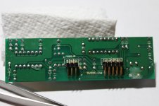
Please show the opposite side of the daughter PCB.
If an oscilloscope is available, check the idle oscillation frequency of the good channel vs. bad channel. Post numbers. Find the source of overheating: too high frequency? Or overlap in FET drive? Or FET damaged due to ESD during replacement? Also compare old/new the type of IRF640, there can be one more letter like IRF640N.
Check the big bipolar electrolytic capacitor, this is a relatively fast aging part.
Last edited:
Thanks for the response Eva.
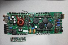
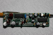
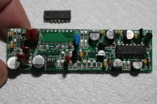
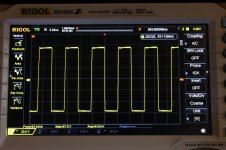
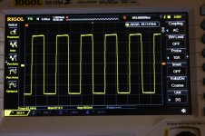
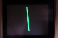
I am unsure which board you are referring too when you say "daughter" board so i will post pics of both the main PCB and plug in oscillator board. Also attached are the pic's of the O'scope on both channels. They seem to be well within operating range. I removed the two large 4700 uF caps and ordered replacements. I do not have a cap tester yet but have one on the way. I'm going to go ahead and pull all the electrolytic cap's and get them out of the equation.
I am unsure which board you are referring too when you say "daughter" board so i will post pics of both the main PCB and plug in oscillator board. Also attached are the pic's of the O'scope on both channels. They seem to be well within operating range. I removed the two large 4700 uF caps and ordered replacements. I do not have a cap tester yet but have one on the way. I'm going to go ahead and pull all the electrolytic cap's and get them out of the equation.
16-mc1000d
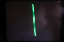
Also included are the trace signatures for the two output electrolytics. I can not vary the voltage for a better representation. Maybe that will be my next project ! The replacements for the output fets are the IRF640NPBF variants. I had compared them and the differences seemed an improvement.
Also included are the trace signatures for the two output electrolytics. I can not vary the voltage for a better representation. Maybe that will be my next project ! The replacements for the output fets are the IRF640NPBF variants. I had compared them and the differences seemed an improvement.
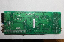
Of course I meant the daughter PCB with the unknown IC. I'm having trouble recognizing that IC too, maybe drawing the circuit... I don't think these manufacturers can (or are required to) afford custom ICs.
By "class D output capacitor" (not the 4700uF bulk capacitors) I meant the big 2x 10uF 200V (maybe non-polar? can't see color band).
Is the 1st oscilloscope picture (left to right) from the channel that overheats? The little peak at the end of the low-to-high transition suggests (unexpected current peak) timing is suboptimal or there is something different between halves of the full-bridge ("channels", actually using same clock and inverted logic drive signal). Low side gate waveforms (the easier to obtain) will reveal if there is excessive overlap.
- Status
- This old topic is closed. If you want to reopen this topic, contact a moderator using the "Report Post" button.
- Home
- Amplifiers
- Class D
- 16-MC1000D Parts Problem