In the D amp thread, Windforce85 noted:
Windforce's tongue-in-cheek is perfect:
no a in -less D/A A/D conversions is better
low power -I only need 10 - 20W for tweets and hi eff mids
cheap -Cheap, small and low ext comp is GOOD
unsolderable -If you can find a good eval or diy ...
Great addition to an all digital system.
Perfect for tweeters and high eff mids!
"Description
The TAS2770 is a mono, digital input Class-D audio
amplifier optimized for efficiently driving high peak
power into small loudspeakers. The Class-D amplifier
is capable of delivering 15.4 W of peak power into a
4-Ω load while sustaining 11.6 W continuously with
less than 0.03 % THD+N at a battery voltage of 12.6
V.
Integrated speaker voltage and current sense
provides for real time monitoring of loudspeaker
behavior. A battery tracking peak voltage limiter with
brown out prevention optimizes amplifier headroom
over the entire charge cycle of 2S or 3S battery
systems.
Up to eight devices can share a common bus via
either I2S/TDM + I2C."
from
http://www.ti.com/lit/ds/symlink/tas2770.pdf
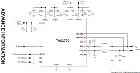
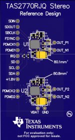
Stereo EVM Layout Diagram
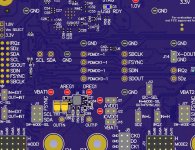
Stereo EVM Layout Reference Design - 01
Cheers,
Jeff
http://www.ti.com/lit/ds/symlink/tas2770.pdf
This is not for 'real audiophiles' becouse:
- It lacks analogue inputs (you cannot put your fancy stuff between source and amp anymore) .
- Power is limited to circa 10-20W (you will not be able use it as a heater in winter conditions or to weld speaker cables with 1kW RMS power).
- It's dirt cheap, too small, to little external components (you have no place to put WIMA's and Coilcraft).
- You cannot solder it at your workshop.
But...
- It uses PFFB loop with I/V kelvin sensing at the outputs.
- Declares 32 uV A-weighted output noise.
- Low and clean THD+N versus power .
- Finally beautifully consistent THD+N versus frequency.
- 90 dB worst-case PSRR.
- I2S input so you can do what you want with DSP before it.
Audio performance is on pair with NCxxxMP modules at least not the power. I am curious what about the sound?
Lovely solution for portable battery-powered or compact, low-power systems.
Windforce's tongue-in-cheek is perfect:
no a in -less D/A A/D conversions is better
low power -I only need 10 - 20W for tweets and hi eff mids
cheap -Cheap, small and low ext comp is GOOD
unsolderable -If you can find a good eval or diy ...
Great addition to an all digital system.
Perfect for tweeters and high eff mids!
"Description
The TAS2770 is a mono, digital input Class-D audio
amplifier optimized for efficiently driving high peak
power into small loudspeakers. The Class-D amplifier
is capable of delivering 15.4 W of peak power into a
4-Ω load while sustaining 11.6 W continuously with
less than 0.03 % THD+N at a battery voltage of 12.6
V.
Integrated speaker voltage and current sense
provides for real time monitoring of loudspeaker
behavior. A battery tracking peak voltage limiter with
brown out prevention optimizes amplifier headroom
over the entire charge cycle of 2S or 3S battery
systems.
Up to eight devices can share a common bus via
either I2S/TDM + I2C."
from
http://www.ti.com/lit/ds/symlink/tas2770.pdf

Stereo EVM Layout Diagram

Stereo EVM Layout Reference Design - 01

Cheers,
Jeff
Last edited:
This is the first class D amplifier (after NCore) which is free from THD rise at high frequency. What is more, first monolithic and first one with digital inputs. This, paired with PFFB promises really interesting amplifier especially for high efficiency mids and tweeters. In modern multi-way DSP-powered systems you can freely add any of powerful multi-Watt Class D amp for your woofers without bothering about trebles performance.
I have negative experience with amplifiers showing significant THD rise at high frequencies. They could have record-low 1 kHz distortion number but every time there was something wrong with them while focusing attention on trebles. Class D has ability to control low-frequency transducers very well so we all tend to distract our attentions from weak highs. Lack of long analog input path which is prone to many problems is, for me, another plus.
But... who can DIY manufacture this hardcore PCB arrangement and chip package?
This is the first class D amplifier (after NCore) which is free from THD rise at high frequency. What is more, first monolithic and first one with digital inputs. This, paired with PFFB promises really interesting amplifier especially for high efficiency mids and tweeters. In modern multi-way DSP-powered systems you can freely add any of powerful multi-Watt Class D amp for your woofers without bothering about trebles performance.
I have negative experience with amplifiers showing significant THD rise at high frequencies. They could have record-low 1 kHz distortion number but every time there was something wrong with them while focusing attention on trebles. Class D has ability to control low-frequency transducers very well so we all tend to distract our attentions from weak highs. Lack of long analog input path which is prone to many problems is, for me, another plus.
But... who can DIY manufacture this hardcore PCB arrangement and chip package?

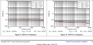
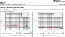
THD vs f flat at 0.1 W, 1W, and 5W!
Last edited:
It dissipates maximum 1W per channel and is super-small. Designed for battery operation right from the start. Modern lo-impedance, high current Li-Ion chemistry opens the doors of new generation, clean and silent power supply. Why even bother about this while having well over 90 dB PSRR???
It makes of really interesting conception self-contained digital transducer: You can put it EVERYWHERE. Micro-cubic liter sealed cabinet. Lithium battery pack inside. The only connection with outside world - microUSB socket for charging and hi-res USB-audio (384 kHz capable!) data transfer. For lazy men you can add BT or Wi-Fi... The future is here.
It makes of really interesting conception self-contained digital transducer: You can put it EVERYWHERE. Micro-cubic liter sealed cabinet. Lithium battery pack inside. The only connection with outside world - microUSB socket for charging and hi-res USB-audio (384 kHz capable!) data transfer. For lazy men you can add BT or Wi-Fi... The future is here.
Last edited:
Yeah they look like cannot be true. But imagine it is powered from low impedance Li-Ion battery pack. Low noise, low impedance voltage source which is close to ideal PSU considering its price and performance when someone knows how to design and use it. Why bother is it 60 or 90 dB PSRR then?
Finally we are getting rid of over-built analogue stages, too many conversion stages, and we can focus on front-end performance which is mostly related to transducer itself. The transducer has greatest influence on overall audio performance. If not using this new amp like full-band power-hungry device, you can imagine it being like part of linear-array DSP loudspeaker or like med-hi band amplification using modern neodymium strong and efficient drives. In contrary, low to mid frequencies where stroke matters, can be covered by more-common class D amplification this is where sheer power matters.
Finally we are getting rid of over-built analogue stages, too many conversion stages, and we can focus on front-end performance which is mostly related to transducer itself. The transducer has greatest influence on overall audio performance. If not using this new amp like full-band power-hungry device, you can imagine it being like part of linear-array DSP loudspeaker or like med-hi band amplification using modern neodymium strong and efficient drives. In contrary, low to mid frequencies where stroke matters, can be covered by more-common class D amplification this is where sheer power matters.
Last edited:
This is the first class D amplifier (after NCore) which is free from THD rise at high frequency.
The Ncore does not do this, it does exhibit a high frequency rise if measured in a way that can display it. Bandwidth limiting is used for hypex's datasheet measurements. Of course TI do the same thing, but when the measurement bandwidth goes up, and the third harmonic beyond ~8kHz can actually be measured properly, the THD shoots up.
What is more, first monolithic and first one with digital inputs.
Do not confuse this for anything special. The chip simply contains on on-board DAC, there's no difference to using a separate DAC + comparable, analogue input, class D amplifier. Of course it simplifies some things but that's about it.
This, paired with PFFB promises really interesting amplifier especially for high efficiency mids and tweeters.
How are you going to add PFFB to this amplifier? The built in I/V sensing is to add limiting to protect the loudspeaker. If you look at the performance plots you can see that employing the sensing system degrades the amplifiers performance rather significantly.
Proper PFFB is supposed to linearise the amplifier, not de-linearise!
I have negative experience with amplifiers showing significant THD rise at high frequencies.
I guess you don't like virtually all class A/B amplifiers either then!
But... who can DIY manufacture this hardcore PCB arrangement and chip package?
I could work with the QFN package (build and solder my own PCBs) if I had to. They aren't the easiest of things to solder but it can be done.
Still the performance of this low power class D chip amp is a significant improvement over pretty much every other similar product that TI have ever released. Noise and THD are a decent improvement.
It will need a proper output filter for a hifi application, where speaker cables will get longer than around 1 meter, otherwise EMI is going to be an issue. Although EMI worsens at high output power levels and when the device is operated from high voltage rails.
What intrigues me though is the overall performance of the class D amplifier module inside the chip. This seems to have many things going for it over what you'll find inside TIs TPA311x and their next generation replacements. The flat THD (measurement limitations notwithstanding) does appear to do something that the others do not. It would be nice to see an analogue input version with only the class D unit inside.
From a performance point of view though you'd be far better off combining a PCM5242 and TPA3244. Two chips of course, but with the TPA3244 you really are free to include post filter feedback for the proper gains that it brings. The PCM5242 is a balanced stereo DAC with DSP processing (if you want it) and can input directly into the 3244 keeping analogue signals very short.
The 3244 (and the rest of that series) might show rising THD with frequency but TIs graphs don't show they entire story.
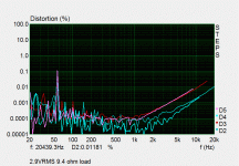
The image I've attached shows the performance of a PFFB TPA3251 amplifier that I've built. This is for roughly 1 watt into 9.4 ohms. As you can see the midband distortion is far lower than TIs datasheet would lead you to believe. These are distortion measurements not distortion plus noise. Clearly TIs measurements are noise dominated at lower power levels, but my measurements show you the HD spectra, rather than just the THD.
As you can see the distortion is extremely low but shows the typical odd order rise with frequency. The BTL configuration helps to cancel out the even order harmonics, leaving the odd orders to shine through. These amps are really 3rd and 5th order dominant but when 20kHz bandwidth limiting is imposed you don't get to see how much they rise, especially if noise is dominating the measurements at low power levels.
What's impressive about the TAS2770 is that it does appear to keep it's distortion lower at high frequencies in a way that the Purepath UltraHD parts do not. Of course I am referring to the diagrams labelled figures 10 and 12. Where I/V sensing is used (figures 27 and 31) the distortion + noise has risen quite considerably, yes it's flat, but the level is high. I can't imagine this is because of gross noise levels, so it must just be high distortion from some mechanic integrated into the protection scheme.
Figure 32 is what interests me because here we are seeing the typical rising distortion that quickly falls away at 7kHz due to the third harmonic falling out of the measurements bandwidth. This is the 1 watt with 4.5V supply right? Why is it missing elsewhere with the 4.5V supply? The typical distortion rise is due to the amount of internal feedback being reduced for stability, so linearity decreases. This affects all amplifiers, be they class A, AB or D, just to different degrees.
Analogue Devices has an interesting part called the SSM3582 that you might be interesting in looking at too. It's very similar to the TAS2770.
Attachments
Happy new year doc!
I am, as we speak, working on a three channel PFFB design with the TPA3244. One part in BTL, one in PBTL. It'll be interesting to see how this one does! Using your cap recommendation for the bulk decoupling. The GPD series from Nippon, a step above Panasonics FC series, what I was using, but of course you pay for this!
One thing I've pondered a couple of times is would a composite amplifier be possible with some of these class D chips? Like the composites that use the LM3886 + opamp for vastly improved performance over what the LM3886 can ordinarily provide. Certainly there'd be a handful of headaches to overcome
Thanks for great informative post 5th element!
Yes I also considered TPA3244 becouse from points you have mentioned it looks most promising from analogue point of view. It is funny but I also considered the same DAC.
Thanks for SSM3582 part suggestion - great find! On pair or even better than TAS2770...
Yes I also considered TPA3244 becouse from points you have mentioned it looks most promising from analogue point of view. It is funny but I also considered the same DAC.
Thanks for SSM3582 part suggestion - great find! On pair or even better than TAS2770...
Hello 5th element!
Your findings with distortion of TPA325x look familiar to me. To mask the noise of my soundcard (EMU tracker pre) I decided to measure k2- and k3-levels with ARTA/SPA. These numbers look more informative to me.
Your achievements are outstanding. Would you mind elaborating on stability of postfilter-fb around these chips?
A composite might prove difficult with i2s/tdm/i2c input amplifiers.
I think the LM3886 is very hard to beat when correctly implemented. TPA32xx family is awesome!
Still really want to try the SSM3582, too much going on so I'm still hoping for a GB or something. Have not touched pcb design since 1999/2000, and then only for small stuff.
I think the LM3886 is very hard to beat when correctly implemented. TPA32xx family is awesome!
Still really want to try the SSM3582, too much going on so I'm still hoping for a GB or something. Have not touched pcb design since 1999/2000, and then only for small stuff.
Hello 5th element!
Your findings with distortion of TPA325x look familiar to me. To mask the noise of my soundcard (EMU tracker pre) I decided to measure k2- and k3-levels with ARTA/SPA. These numbers look more informative to me.
Your achievements are outstanding. Would you mind elaborating on stability of postfilter-fb around these chips?
I haven't actually had any problems with stability and pffb. TI have released two application notes for its implementation. The latest includes additional filtering to help prevent instability which the original did not.
For my tpa3251 build this was only done with the first app note but it worked flawlessly and measured stable within TIs guidelines. I did poke the bear, out of curiosity, to see what would happen if the thing did becom unstable though. I omitted the additional zobel and tried the amplifier without a load connected. All that happened was the amp quickly went into protection and shut itself down. Good to know.
A composite might prove difficult with i2s/tdm/i2c input amplifiers.
I think the LM3886 is very hard to beat when correctly implemented. TPA32xx family is awesome!
Yeah a composite would be ridiculously hard to implement using one of the digital input amplifiers. You'd need an ADC for post filter measurements coupled with a DSP. They'd all need to be high speed too, enough to have the bandwidth to correct for higher order harmonics.
I was thinking of composite using the tpa3116 or something from the tpa32xx family. Just out of interest, rather than necessity really.
I am a bit curious as to why the TPA3116 sounds bad to me, my hearing is not that good. May there be some noise issue fed back into the power bank? Even with batteries? Could the TPA3116 feed noise to itself?
If that is the case: Maybe it is possible to use op amps to negate the noise? Would probably require another isolated low noise power supply though, maybe two, one for + and one for -.
At any rate, you already have the '3251 going. How much does it gain from 0 noise psu? PSSR is rated 60db, so there should be some benefit at least. BTL shows lower integrated noise than SE (60uV vs 115uV), maybe there is some cancellation because of small internal/external difference in track lenght? Does noise change with switching frequency? Which influences noise floor most; VDD/DVDD/AVDD or PVDD?
It's getting difficult to measure the low noise on this stuff already, but who knows, there might be some benefit getting to -200db noise floor...... *insert manic smile*
But as I've recently started to experience (the last 4-5 years or so), 1db here is not 1db over there. Signals, filters, gain setting, absolutely everything seems to change with just tiny variations. I feel I'm starting to get crazy, for instance: it seems to me that sometimes q of dsp filters change with gain settings. 1 db of difference completely ruins the whole thing in one place, and 3db difference in another place is not perceived at all. Maybe some data is missing, there must be something relevant we are not measuring somewhere.
Sorry about the OT.
Last edited:
I am a bit curious as to why the TPA3116 sounds bad to me, my hearing is not that good. May there be some noise issue fed back into the power bank? Even with batteries? Could the TPA3116 feed noise to itself?
Typically speaking power supplies are quiet, even switching supplies, unless they are of poor construction, or have been designed with gross compromises in mind, due to the tolerant nature of what they are powering.
What makes supplies noisy is noise feeding back into them from the various devices that they are powering. Keeping noise from one device, from feeding into another device, both on the same supply, is often something that needs specific attention being paid to.
Directly in line with this are issues with keeping the other side of the supply clean, the ground, or return paths. Just like supplies these start out clean but end up noisy because of the devices they are connected to. Again, lots of effort is usually put into PCB design and layout to make sure that problems aren't encountered, or at least minimised to within acceptable levels.
Now the TPA3116/8 is relatively simple and, in general terms, doesn't have particularly low levels of distortion. I doubt that systemic noise, being apparent as noise on the outputs, would be any major concern, nor would I expect any systemic noise to be be responsible for causing excessive distortion here either.
This isn't to say that it's not possible, but it's unlikely, at least from the point of view of severely compromising the devices potential.
If that is the case: Maybe it is possible to use op amps to negate the noise? Would probably require another isolated low noise power supply though, maybe two, one for + and one for -.
This isn't where these problems tend to show up. The kind of noise that we're discussing here is switching noise, generated by the output stage of the TPA, finding its way back into the input stage of the TPA itself.
TI are aware of these issues themselves and making devices easy to use is important to them. If any special requirements were necessary to extract the performance that the device is capable of then it would be written in an application note or the datasheet.
At any rate, you already have the '3251 going. How much does it gain from 0 noise psu? PSSR is rated 60db, so there should be some benefit at least.
As with any circuit a noisy PSU has an impact on the overall performance. The sensitive analogue side of the system needs a clean supply. The output stage also needs a relatively clean supply but it also needs a low impedance supply for the absolute best in performance.
BTL shows lower integrated noise than SE (60uV vs 115uV)
Yes because the bridged nature of BTL configuration helps to cancel out noise and some forms of distortion.
Does noise change with switching frequency? Which influences noise floor most; VDD/DVDD/AVDD or PVDD?
DVDD and ADVV are internally generated. These are supplied by VDD, which needs to be clean and needs isolation from GVDD.
Generated system noise essentially changes with everything relevant to what the part does. Correct design and usage of the part helps to make the noise sensitive parts of the chip immune to these changes.
- Status
- This old topic is closed. If you want to reopen this topic, contact a moderator using the "Report Post" button.
- Home
- Amplifiers
- Class D
- TAS2770 20W Digital Input Mono Class-D Amp, Speaker I/V Sense, I2S input all digital
