Still curious about other power supplies, though. Anyone have any experience comparing a lower current switching supply to a higher current switcher? Anyone compare a switching supply to a linear supply?
Class D demands for a SMPS, it doesn't align with a linear one *imho*.
As far as I'm informed, the TPA3255's maximum rating for supply voltage is 53.5 Vdc. So, an unregulated linear supply mustn't exceed this voltage, even at idle. As the rectified voltage will sag under load, you'll lose maximum output power. Or you'll generate excess heat in a regulated LPS.
Best regards!
so it looks like i might need to dive into troubleshooting my 3255 evms.. the btl channel on one (ive got 2 amps in 2.1 mode) is significantly louder than the other, and i do appear to have some distortion, although its quite hard to tell 100% by ear with sub frequencies, on drivers that are not yet in enclosures... how much is the amp, how much is the driver..? certainly seems a dirtier sound than id expect. although, as mentioned elsewhere, pure tones from a generator sound clean to my ears.
problem i have now ( apart from needing to take it all apart again for testing) is that i dont have a scope. any of you brains care to suggest what to check and any methodologies i can use to test/diagnose with just a signal source ( tone generator/music on my phone) a multimeter, and some drivers..?
mods i have done (all discussed here first) on each board are:
moved big 4700uf caps to front of board (replacing stock heatsink and rotating output inductors a bit made space)
extended one output inductor on 1.5cm legs to make room for another element.
removed redundant output caps on btl channels.
removed rca jacks
inputs on 3 pin headers
all power/outputs soldered directly to board.
thats about it..
first things to check?
heeelp!
Class D demands for a SMPS, it doesn't align with a linear one *imho*.
As far as I'm informed, the TPA3255's maximum rating for supply voltage is 53.5 Vdc. So, an unregulated linear supply mustn't exceed this voltage, even at idle. As the rectified voltage will sag under load, you'll lose maximum output power. Or you'll generate excess heat in a regulated LPS.
Best regards!
Thanks.
first things to check?
If you switch drivers, does the problem move with the drivers?
With your multimeter set to DC, and no signal, measure the voltage across the driver inputs. It should read very close to zero.
Generate a 60hz signal into the amp, measure the AC voltage across the driver inputs. The output voltages should be the same on both amps.
Mike
thanks for the initial pointers.. ill try that tonight.
tried a pair of bookshelf speakers, thats when difference in volume became noticeable.. distortion wasnt so obvious, but then it seemed to manifest at low frequencies, which the bookshelves are not very good at highlighting!
couple of things.. the distortion is particularly noticeable on transients (kick drums sound awful, pure sine waves sound normal) does this suggest an avenue to investigate? psu is connex 800w 48v.. distortion doesnt seem to change depending on number of channels active, so does not suggest psu problems to me..
ive been looking at a (very) cheap scope this afternoon... would something like this be useful? :
JYETech DSO Coral Pocket Battery-Powered Oscilloscope w/ Color Touch Display (DSO112A): Amazon.com: Industrial & Scientific
i need some what to measure/visualise this distortion i can hear, as im going nuts trying to work out how much is the amp, how much is speakers without enclosures. i do know that distortion improves *enormously* when i lift up subs (unblocking pole vent) but i think they are still distorting.
maybe measurement mic and laptop is the way to go, although that wont isolate the cause..
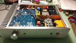
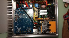
here is my amp, so far.. of course i now need to take it all apart again to troubleshoot!
i know.. the messy soldering. the shifting of the big caps to the other side of the boards was done first, and with a gas soldering iron. I then upgraded to a soldering station so the other soldering is a bit nicer!
its a 30cm x 30cm (approx) case with an 800w smps, 2x 3255 evms , a minidsp2x4HD, and an aptx bluetooth receiver. had i known how crammed it would get inside i would have got a bigger case.. i did layouts in 3d first, but didnt consider how much space fixings, cabling and metalwork take up!
Attachments
Last edited:
I remember your packaging cogitations, but yeah, that looks a bit compromised to squeeze too much into too little space. I'm honestly concerned about cross-coupling of magnetic fields, but that may be unwarranted. That's a lot of EMI floating around though, so it'll be tough knowing if you're running into a board level or package level problem.
* You could probably yank the PSU out and make a super power brick keeping the local bypass in case if you need the space.
* You could probably yank the PSU out and make a super power brick keeping the local bypass in case if you need the space.
yeah thats always been my backup plan. once id bought all the bits i decided to treat it as a challenge (like tetris!)
ive kept all psu related stuff inside a shielded area, and all cables with any ac or signal on them are twisted tightly and shielded (the line level stuff actually has two shields )
)
when its on with no input, i dont get significant noise on the speakers.. just a slight mains hum if i literally touch my ear to the cone.. so it works in that sense.
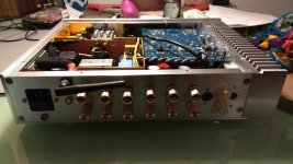
- i even went as far as activating the power switch with a lever/pushrod from the front button. there was no space inside shielded area directly in front of pre-drilled power button location, so i placed it where it would fit inside shield, then added the lever.. works well!
front panel controls for minidsp are hacked in, by adding a stripped down minidsp remote internally, connected to frontpanel controls. ir emitter is placed next to ir reciever on minidsp. would have been simpler if minidsp actually provided a control header on their board!
ive kept all psu related stuff inside a shielded area, and all cables with any ac or signal on them are twisted tightly and shielded (the line level stuff actually has two shields
) when its on with no input, i dont get significant noise on the speakers.. just a slight mains hum if i literally touch my ear to the cone.. so it works in that sense.
- i even went as far as activating the power switch with a lever/pushrod from the front button. there was no space inside shielded area directly in front of pre-drilled power button location, so i placed it where it would fit inside shield, then added the lever.. works well!
front panel controls for minidsp are hacked in, by adding a stripped down minidsp remote internally, connected to frontpanel controls. ir emitter is placed next to ir reciever on minidsp. would have been simpler if minidsp actually provided a control header on their board!
Last edited:
ok so test results:
dc voltage across speakers without input signal:
sub1 =4mv
fullranges 1 and2 = 1mv
sub 2 = 9mv
fullranges 3 and 4 =0mv
ac across speakers with 50hz input signal @low volume (GF watching tv!)
sub 1 =1.32v ac
sub 2 = 1.29v ac
seems to be reasonable..?
dc voltage across speakers without input signal:
sub1 =4mv
fullranges 1 and2 = 1mv
sub 2 = 9mv
fullranges 3 and 4 =0mv
ac across speakers with 50hz input signal @low volume (GF watching tv!)
sub 1 =1.32v ac
sub 2 = 1.29v ac
seems to be reasonable..?
Last edited:
any other tests i can do, specifically for distortion or interference, scope free? i imagine not.
To measure distortion, a soundcard and ARTA is the way to go. If you see distortion on the scope it is way to much. Btw did you consider repeating your measurements without GF watching TV?
hm seems that the bookshelf speakers where i noticed the big l/r discrepancy seem to be defective, or rather, one of them is.... lucky im building new speakers eh?
so ive been listening some more, and i am more and more convinced that these subs just cannot be plaid in free-air above miniscule volumes without sounding awful if touching anything. partly rattling against floor (mitigated by cushion) but mostly from the blocked pole vent (not helped by cushion resting) holding them up they sound much better, still distort if you crank em up a little bit, but maybe thats normal.. i had assumed that under xmax they shouldnt sound distorted if the signal is clean.. but i will hold off until i have them in boxes before worrying about the amp.. only a few weeks till i get the cnc bits back
so ive been listening some more, and i am more and more convinced that these subs just cannot be plaid in free-air above miniscule volumes without sounding awful if touching anything. partly rattling against floor (mitigated by cushion) but mostly from the blocked pole vent (not helped by cushion resting) holding them up they sound much better, still distort if you crank em up a little bit, but maybe thats normal.. i had assumed that under xmax they shouldnt sound distorted if the signal is clean.. but i will hold off until i have them in boxes before worrying about the amp.. only a few weeks till i get the cnc bits back
Bi-amping with active crossover?
Since the EVM can be configured to accept 4 inputs and outputs in SE mode, is it feasible to stick an active crossover between the source and the EVM, and send the 4 outputs to 4 individual drivers? Any potential downsides?
Also, links to active xover designs would be appreciated!
Thanks.
Since the EVM can be configured to accept 4 inputs and outputs in SE mode, is it feasible to stick an active crossover between the source and the EVM, and send the 4 outputs to 4 individual drivers? Any potential downsides?
Also, links to active xover designs would be appreciated!
Thanks.
Both measured performance and subjective sound quality are worse using single ended than using BTL. I bi amp using a modified DBX234XL (discontinued so they are US$20 on Taobao) and 2 stereo BTL amps.
Everything you could want to know about bi-amping including schematics and parts calculator is Here thanks to Rod Elliott.
Everything you could want to know about bi-amping including schematics and parts calculator is Here thanks to Rod Elliott.
Last edited:
Since the EVM can be configured to accept 4 inputs and outputs in SE mode, is it feasible to stick an active crossover between the source and the EVM, and send the 4 outputs to 4 individual drivers? Any potential downsides?
Also, links to active xover designs would be appreciated!
Thanks.
the minidsp 2x4 HD @robinlawrie is using for input stage has excellent crossover, EQ, and filtering capabilities
- Home
- Amplifiers
- Class D
- TI TPA3255EVM