I'm happy with the result.
Enjoy.
...and don't forget to invite your neighbours to the party.
Do you have measurements, waveform data to enlighten us about the very effect you are talking about, since I fail to see a rise in distortion in my multi kilowatt module with ferrite beads. We might learn something new from you?")
Firstly, I did not say it will, I said it can increase distortion. Secondly, the hysteresis of the ferrite beads is, what suppress parasitic oscillation, this is, what you want. What you don't want is to drive the cores into saturation because they drop in inductance if it happens. That causes two things (well, actually more but these are the main issue here), your choke does not work like it did non-saturated, which can cause noise, or oscillation. The second effect it can have is that it might affect the behaviour of the FETs, to be more exact, the rise time can change. That means your dead time, depending on the adjustment you've chosen, might become critical. Again, I did not say it will happen but it can.
Measurements of saturated inductances (not specifically the ferrite beads you were mentioning though): Measurement of coil saturation and inductance | Rauschfunk
The datasheets of the used beads can probably provide information on how close you come to saturation.
Where/How should it increase distortion when mounted over the gate/drain legs and used in this configuration? You're talking about total different effects which occur when using ferrites/inductors iNLINE in high current applications - which totally isn't the case here. The other effect of resonance peaking will need some high Q capacitance after the ferrite.
Last edited:
Enjoy.
...and don't forget to invite your neighbours to the party.
I have made this amplifier for full range speakers in general, but as an immediate application, it will amplify these Seeburg k2 nd (and their clones).
http://www.seeburg.net/pdfs/produktpdfs/K2_Datenblatt_dt.pdf
An externally hosted image should be here but it was not working when we last tested it.
An externally hosted image should be here but it was not working when we last tested it.
The impedance of these speakers requires some resources from the amplifier:
An externally hosted image should be here but it was not working when we last tested it.
Last edited:
This is looking quite satisfactory.
It seems we have some disciplines in common. I have been fully dedicated to creation of next generation of class D amplifiers for 10 years, with no free brain resources for progress in sound systems, but this could change in the future.
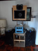
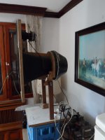
btw: the cabs in the floor are all LF, the smaller driver is closed back, just to cover the hole, and I also happen to have an unfinished 2nd channel, cloned mid horn
It seems we have some disciplines in common. I have been fully dedicated to creation of next generation of class D amplifiers for 10 years, with no free brain resources for progress in sound systems, but this could change in the future.
btw: the cabs in the floor are all LF, the smaller driver is closed back, just to cover the hole, and I also happen to have an unfinished 2nd channel, cloned mid horn
Attachments
I think there is a misconception here. A hobby is a nerd renting a system from a nerd, to play popular mass market tracks made by and for nerds, who pay the renting and some more, as the only way to enter in contact with exemplary designs and philosophies. Producing the high tech personally is a though discipline.
Somehow the horn on the floor is catching my immediate sympathy.the cabs in the floor are all LF
Is it wrong to do so not for money but for joy+brain food and calling it a hobby?Producing the high tech personally is a though discipline.
I think there is a misconception here. A hobby is a nerd renting a system from a nerd, to play popular mass market tracks made by and for nerds, who pay the renting and some more, as the only way to enter in contact with exemplary designs and philosophies. Producing the high tech personally is a though discipline.
My so-called hobby, I have mentioned, includes besides making various speaker constructions and processing their sound either by making passive filters or choosing a combined passive-active filtering method, or full active filtering and processing . The real challenge is to make a speaker sound good, or sound like another speaker taken as a reference, knowing and identifying correctly what are the acoustic anomalies and which ones can be corrected acoustically (through various modifications, including but not limited to shape changes, addition of sound absorbing material, surface damping, addition of acoustic reflectors, horn shape change for the driver, etc.), or electric through the various filtering and equalizing methods, taking into account the directivity of the speaker as a whole. Last but not least, considering that each speaker has a specific timbre, sometimes portions of the frequency range that do not sound properly, these shortcomings must be identified, and the total measured acoustic response may not resemble that of another speaker to sound the same. There is much to say, but I stop here because I do not want to completely change the direction of this topic.
Now, that's what I call hobby.
 Some posts have been removed. Reactance your initial comment was insulting, and produced the expected response. Eva you need to avoid political commentary. Further exchanges of this sort will result in points and/or bin time for all parties involved.
An externally hosted image should be here but it was not working when we last tested it.
Not really bad, 1600-1800w / 3.8r / 50hz. But after a few probes of 5-7 seconds each, the mosfets have died ... the temperature of a small radiator has risen over 70 degrees. What do you think are the causes? Qrr?
I think increasing the heat sink is not a proper solution if you want to enable a classD switching stage of this voltage and power level in a reliable way for continuous power.
Note: Many designs in the market are not enabled for such, but reduce power after few hundrets ms.
IMHO there are two reasons which fit to your observation.
- Switching losses due to slow current commutation, which you must keep slow because of the layout.
- Switching losses due to the Qrr of the body diodes.
The body diode is specified with a Qrr of 844nC-1689nC at 25C and di/dt=100A/us. If you assume a hot junction and di/dt around 300A/us you can easily expect a Qrr of 3000nC, unfortunately the data sheet gives no information under realistic operating conditions.
The resulting losses are immense.
If you want to get this right with silicone MosFets for continuos power delivery you will need to go for a series shottky which avoids Qrr to be charged plus a fast freewheling diode. Qspeed Qseries is looking promising, but I never tried them.
Qspeed Q-Series Diodes | Power Integrations - AC-DC Converters
Or you step to SiC...
I did not calculate in detail, but I guess something like two Cree C3M0065090 in parallel for high side and low side as well would be a starting point.
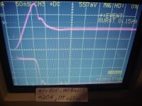
Attached two screen shots which show the hard switching including the removal of Qrr. Both were taken with a modified LiteAmp (Nickname: LiteNerd).
First screen shot is with IRFB4227 powered from +/-83V (sagging to +/-80V) with a load current of -20A (sinking).
In order to remove Qrr an additional 20A peak leads to a total current peak of almost 40A while the Vds still equals almost full rail.
Under this load condition it takes slightly less than one second until
the junction reaches something like 175C , then the Vds drop becomes large enough to trigger the shut down of the IRS2092 and the LiteNerd turns off without defect.
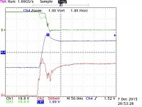
Second screen shot is with C3M0065090 powered from +/-83V with a load current of -25A (sinking). Here the additional peak is shorter and adds just about 6A.
Compared to your 300V MosFets the advantage of the SiC will be again more noticeable.
Screen Shot 1 (IRFB4227):
Upper trace: Id, 10A/Div.
Lower trace: Vds, 50V/Div
Screen shot 2 (C3M0065090):
Channel 1: Vds plus voltage drop of current probe, 100V/Div
Channel 3: Vds directly at the pins of the Fet, 100V/Div
Channel 4: Id, 10A/Div.
Channel 2: Vgs, 5V/Div.
Note:
In a professional design one should provide slightly negative Vgs during off time for the C3M0065090, but on the bench it works fine with more or less zero.
First screen shot is with IRFB4227 powered from +/-83V (sagging to +/-80V) with a load current of -20A (sinking).
In order to remove Qrr an additional 20A peak leads to a total current peak of almost 40A while the Vds still equals almost full rail.
Under this load condition it takes slightly less than one second until
the junction reaches something like 175C
, then the Vds drop becomes large enough to trigger the shut down of the IRS2092 and the LiteNerd turns off without defect.Second screen shot is with C3M0065090 powered from +/-83V with a load current of -25A (sinking). Here the additional peak is shorter and adds just about 6A.
Compared to your 300V MosFets the advantage of the SiC will be again more noticeable.
Screen Shot 1 (IRFB4227):
Upper trace: Id, 10A/Div.
Lower trace: Vds, 50V/Div
Screen shot 2 (C3M0065090):
Channel 1: Vds plus voltage drop of current probe, 100V/Div
Channel 3: Vds directly at the pins of the Fet, 100V/Div
Channel 4: Id, 10A/Div.
Channel 2: Vgs, 5V/Div.
Note:
In a professional design one should provide slightly negative Vgs during off time for the C3M0065090, but on the bench it works fine with more or less zero.
Attachments
Last edited:
Power testing is a discipline on its own. There are 3 facts to determine.
1- The reliability at high temperature. This is a matter of heating the heatsink to at least 90~100C slowly (test temperature), with moderate continuous power. Then, high current burst capability has to be tested. The circuit shall handle bursts of maximum output current (as allowed by over-current protection), with duty cycle adjusted for keeping the heatsink at about test temperature (as allowed by overheat shutdown or limiting). The test should extend for hours or days to ensure no component degradation, apart from checking proper temperature of all components. In high power professional amplifiers performing this "burn-in" test is recommended in an unit by unit basis.
2- Short term power handling. This is the amount of time maximum power can be sustained, starting with heatsink at ambient temperature, before some thermal protection or limiting is activated. My preference in this field is a feed-forward thermal limiter allowing only 3:1 crest factor in current waveform, past a period of 3 seconds, as this serves both as voice coil protection and relaxes the minimum requirements of thermal coupling between FETs and heatsink.
3- Long term power handling. This is the amount of power the amplifier can produce for an indefinite period of time (thermal equilibrium reached down to measurement resolution), at a certain ambient temperature, without incurring in shutdown or limiting.
For your particular case: 2 FETs at 1700W/3.8r and this voltage can easily dissipate about 90W each (90% efficiency), at full duty cycle. This implies some limitations. Thermal resistance junction-case is rated at 0.5C/W max for IPP FET used. Lets assume thermal grease and gentle tightening torque is used (so that 0.5C can be assumed as junction-heatsink thermal resistance). For a dissipation of 90W the die of the FET can be 45C hotter than heatsink. With heatsink at 70C over ambient (90C) the die can be at 135C. What does it happen with FET Rds-on as temperature increases? From 25C to 135C Rds-on can be multiplied by between 2 and 2.5. This has to be carefully studied with appropriate math. A single pair of TO-220 at this voltage level (and load) is good for full range music (under 3:1) crest factor, for sure, relying on the RMS limiters of a digital crossover for overload attempts. But do not attempt continuous power test without proper study and proper limiting circuits. You have seen the result. Also, you have probably seen the result of no "shorted FET shutdown/emergency current limiting" although you do not comment it: destroyed prototype, often with popped ICs and fused PCB tracks hehe
Last edited:
To moderators: Thanks for your efforts in cancelling out the influence of politics. This is not easy in all countries or at all times. Obviously Reactance was having trouble cancelling the influence, as there are a lot of wrong things happening around. I have experienced that situation too, often causing delays in work. When essential changes are about to happen pressure is at its worst.
- Home
- Amplifiers
- Class D
- Class D amp with 300v mosfets