My issue now , of course, is that site does not appear to list component values. i guess you have to pay for those, and likely they depend heavily on the voltages used, and the switch-on delay required.
given a diagram with component values my skills stretch to building the thing on a veroboard, but when it comes to circuit design, im completely in the dark
anyone feeling *extremely* generous?
PM me if "negotiations" are required.
given a diagram with component values my skills stretch to building the thing on a veroboard, but when it comes to circuit design, im completely in the dark
anyone feeling *extremely* generous?
PM me if "negotiations" are required.
thats very very helpful.
so, the small transformer.. any specific voltage i should be aiming for?
something like this ok?
http://www.conrad-electronic.co.uk/...mer-1-x-230-V-2-x-9-Vac-045-VA-26-mA?ref=list
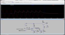
also, where you have written output, there is just a resistor to ground. i assume the relay is driven from a connection at that corner there before the resistor?
one other concern, if i run this circuit from the 12v supply for the minidsp, this is basically bringing an unregulated raw ac connection (from the "trigger" trafo) into the regulated dc side of the amp.
is there any potential to introduce 50hz hum into my system?
so, the small transformer.. any specific voltage i should be aiming for?
something like this ok?
http://www.conrad-electronic.co.uk/...mer-1-x-230-V-2-x-9-Vac-045-VA-26-mA?ref=list
also, where you have written output, there is just a resistor to ground. i assume the relay is driven from a connection at that corner there before the resistor?
one other concern, if i run this circuit from the 12v supply for the minidsp, this is basically bringing an unregulated raw ac connection (from the "trigger" trafo) into the regulated dc side of the amp.
is there any potential to introduce 50hz hum into my system?
Last edited:
What's the miniDSP board supplied with? 12V DC or AC?
Either way, if you look carefully, there's no real (direct) connection between the trigger signal and the 12V itself.
And weren't you saying you'd want to use the "output" to drive the mute signal on the 3255 chips?
Regarding the "trigger" transformer, the smallest (and cheapest) one you can get is plenty, you only need something up to 1mA tops. Worst case, you might need to adjust that R3, depending on the voltage, but that's about it.
You need SOME capacitance there to have some reserve "juice" to keep Q2 and thus Q3 "open" so that current can flow through them. Otherwise the "output" signal would be bouncing on and off, 50 times a second. I assume that would be an undesirable result
Or are you implying that 6ms (6 thousandths of a second) is somehow not fast enough?
the minidsp uses DC..
im planning (until somebody points out my error) to use the 15v aux supply from the smps through something like this:
Amazon.com: Icstation DC to DC Voltage Regulator Step Down Up Power Supply Converter Module 3.5V-28V to 1.25V-26V 3A LM2596 XL6009: Industrial & Scientific
to get a regulated 12v.
wrt driving the "reset" of the amps, i was imagining using a small relay to do this.. keep the amps isolated from the other supplies around. if i understood the datasheet well enough, the reset pin needs to be grounded to put the amp into standby/off.
and yes.. i think 6ms is probably fine
You're being a bit (too) "paranoid" about the potential for hum induction
There's no reason to galvanically isolate the simple pulling-down of the reset pin of the chips. "Guilding the lily" would be a gross understatement
If anything, apart from being pricey and overcomplicated, using that DC-DC converter would actually risk INDUCING noise into the line-level stages As if the electrical noise from the amps themselves wasn't enough...
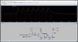
There's no real need to have a particular voltage there. If the reset pins need pulling down, all you need is two more 10k resistors and an NPN transistor; job done
Or if i think about it... You might actually only need to eliminate Q3, and use Q2 as the pull-down switch itself
There's no reason to galvanically isolate the simple pulling-down of the reset pin of the chips. "Guilding the lily" would be a gross understatement
If anything, apart from being pricey and overcomplicated, using that DC-DC converter would actually risk INDUCING noise into the line-level stages
As if the electrical noise from the amps themselves wasn't enough...There's no real need to have a particular voltage there. If the reset pins need pulling down, all you need is two more 10k resistors and an NPN transistor; job done
Or if i think about it... You might actually only need to eliminate Q3, and use Q2 as the pull-down switch itself
Attachments
Last edited:
the dc-dc was to provide the regulated 12v (and several watts) needed by the minidsp and bluetooth receiver boards.
the smps is available with a 12v regulated AUX output as well, but for some reason, i can choose either 2x 5v @500ma, 2x 12v@200ma (not enough for minidsp and BT reciever)
or 2x 15v@400ma (sufficient)
so i thought of going with the 15v version and stepping down to 12v.
the smps is available with a 12v regulated AUX output as well, but for some reason, i can choose either 2x 5v @500ma, 2x 12v@200ma (not enough for minidsp and BT reciever)
or 2x 15v@400ma (sufficient)
so i thought of going with the 15v version and stepping down to 12v.
oh and i think my paranoia comes from not really knowing what im doing!
i know enough to know that interference and hum can sneak in from many places, so i was just doing my best to keep everything as compartmentalised as possible.
any chance you could quickly sketch how those three teeny little extra components should be arranged? i really am useless.. i was better with electronics back when i was 13 years old
How much current does the bluetooth receiver need? Spec sheet for the minidsp 2x4HD says it draws 2.5w, which at 12v translates to about 0.2A - well within the range of a lowly 7812 linear regulator
That would be "burning" about 0.6w (0.2A x 3v drop, from 15v to 12v). With the 65C/W junction-to-ambient thermal resistance (ie. with no heatsink at all), that would mean the die would sit about 40C above ambient. The ambient would need to be well over 50C before that becomes any sort of a problem.
Why (over)complicate things?
PS: The 3.3v "V3" voltage source, along with that 10k resistor there were meant to play the role of the (internally?) pulled-up reset pin, inside the 3255. I haven't browsed the datasheet in great detail, but i remember the internal "Vreg" of the (possibly closely related, but older) TAS5630 chips was 3.3v.
Would you prefer through-hole, or SMD?
Last edited:
ok.. nope, thats not the only thing im confused about. looking at the scope above your schematic, it seems the reset is going to ground when the amp should be running.. this is the opposite of correct behaviour. i *think* the reset should be grounded when amp is off or shutting down, and floating when amp is on.. or possibly at + but im not sure from the datasheet.
edit.. through-hole will be fine.
hehe.. no seriously feel free to stop wasting your brain on me whenever you want. ill find a way somehow.. likely hacky as hell, but ill get there.
some might say that a person with no electronic design skills has no place building an amp.. and they might well be right. however i do love building stuff, and in the major part its all just plugging pre-made modules together in a nice box, and optimising the mechanical layout. now that .. i can do!
cheers, Robin.
Last edited:
What a nice guy! I dont think i could hope for clearer instruction. Now i can let you get back to whatever you woukd rather be doing, and post back when ive built something. I can probably have a stab at this while i wait the 1 month for my smps to arrive. Have a lovely night.. Cheers, Robin.
as per my previous link to a small transformer, the smallest ones i can find for sale here are those, or similar:
PCB Transformers | RS Components
0.35VA seem to be the smallest easily available.
PCB Transformers | RS Components
0.35VA seem to be the smallest easily available.
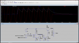
This one should fit the bill just right - VB 1.0/2/6 | 6V ac 2 Output Through Hole PCB Transformer, 1VA | Block
You can use just one of the secondaries, or parallel them up (mind the phase though, check the datasheet).
You can use just one of the secondaries, or parallel them up (mind the phase though, check the datasheet).
- Status
- This old topic is closed. If you want to reopen this topic, contact a moderator using the "Report Post" button.
- Home
- Amplifiers
- Class D
- Pop-free startup/shutdown