ok i have ordered two of those amps.
thanks a lot for the advice and help.
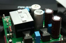
looking at the board layout sent earlier, it seems that just adding a couple of horizontal wires from the solder pads on the top of the board, 1cm or so in length, with the supplied caps attached to them (i.e shifting the caps to the top face, and laterally, diagonally away from the inductors.) should allow them to be fitted, assuming the heatsink is removed.
if it appears this wont work i will look at purchasing the suggested alternatives.
thanks a lot for the advice and help.
looking at the board layout sent earlier, it seems that just adding a couple of horizontal wires from the solder pads on the top of the board, 1cm or so in length, with the supplied caps attached to them (i.e shifting the caps to the top face, and laterally, diagonally away from the inductors.) should allow them to be fitted, assuming the heatsink is removed.
if it appears this wont work i will look at purchasing the suggested alternatives.
now tht is an *extremely* helpful idea!
i must admit im surprised you can remove *all* those big capacitors.. none of them are needed for stereo operation?
that would also have the effect of reducing the overall height to the point where i might not even need to place the big caps on the front face... (consider ill be removing the heatsink, all the bulky connectors for power and output and soldering to the board.)
the tallest elements in this case would be the inductors.
A nice dutch composite 3886 amp was made into same cabinet. Heatpipes to use the heatsink ") But you might be able to mount standard evm boards with heatsink against topplate and cut holes in bottom for fat caps, you'll need holes for airflow in bottom anyway I guess..
But you might be able to mount standard evm boards with heatsink against topplate and cut holes in bottom for fat caps, you'll need holes for airflow in bottom anyway I guess..
http://zelfbouwaudio.nl/forum/download/file.php?id=109472&mode=view
But you might be able to mount standard evm boards with heatsink against topplate and cut holes in bottom for fat caps, you'll need holes for airflow in bottom anyway I guess..http://zelfbouwaudio.nl/forum/download/file.php?id=109472&mode=view
well i dont know about custom heatpipes, no idea how youd even get them made!
but i intend to mount a custom aluminium plate to chip, which will be bolted to side heatsink. given the low heat output of these chips, im sure it will be sufficient.
i intend to direct all heat to the outside of the case this way.. i will be doing the same for the psu, removing heatsink and connecting to case with an aluminium bracket.
(although that will be connected to the top or side plate of the case on the opposite side to the amps. i think that should be sufficient.
i believe the case has some small vents top and bottom, which should take care of any residual heat.
thats a nice amp by the way
Last edited:
now tht is an *extremely* helpful idea!
i must admit im surprised you can remove *all* those big capacitors.. none of them are needed for stereo operation?
These 4 capacitors are for SE operation only (4 channel mode).
something is a bit screwy with that pcb layout you sent doctormord... im doing the amp case layout in 3d, and ive cropped it to the edges, mapped it onto a plane with the dimensions given for the pcb in the design document, and the caps are all oval shaped.. the only sensible explanation i can see is that the pcb dimensions are wrong. the only alternative is the drawing was done with the caps drawn as ellipses not circles.. hardly likely. according to the design doc it should be 140mm x 120mm.
what do you think?
what do you think?
going by the diameter of the larger capacitors given in the BOM, assuming the circles on the pcb layout match the size of the caps, i can scale it in my 3d software until the circles in the schematic are round, and the right size.. that gives me a pcb size of 150 x 115
is that correct?
is that correct?
looking at the size of the chip, and based on my experience with PC watercooling.. i find it hard to imagine getting up to 60w of heat off that chip through such a tiny surface area!!! its miniscule!
a typical pc chip housing is many, many times bigger, and shifting 1-250w from it , you still have a 20 odd degree delta between chip and heatsink temperatures.
at the other end of the scale a typical modern gpu can pull 300-400w, but its so big that cooling is much easier.. delta is much smaller...
this... i just... its soooo small!
yeah im aware of that, but still its good to design for worst-case heat load, which, looking at the docs, for a 4 ohm load and a nasty sinewave at full power, is close to 80 watts!
obviously real-world use would be way, way less than this, i appreciate that.
im really just amazed that you can cool anything with such a small thermal pad.
obviously real-world use would be way, way less than this, i appreciate that.
im really just amazed that you can cool anything with such a small thermal pad.
You can't. Even the EVM can't be run at full power for more than a few minutes. The load tests are done with modified active cooled heatsinks.
Beware that the power/thermal pad is more like a heatspreader as the output stage fets just consume like 30% of the pad dimensions, so the heat conduction path is much smaller than what you see on the chip package. That is why you'll need overmilled pollished heatsink contact without any thermal pad.
I'd do the math for 100% load but then derate for real-world-use. I did that in the past, and you'd need something like 0.5K/W which is hard to hit without forced cooling. The actual implementation is doing ~1.5-2K/W passive cooled.
well im not suree how much maths i can do.. i dont have a spec for the heatsink.
this is the case i wish to use:
http://www.audiophonics.fr/en/alumi...x-case-with-heatsink-320x248x70mm-p-9961.html
the two EVM boards will be mounted back-to-back on opposite sides of a 2x4cm thick aluminium bar, the end of which (area 8cm2) will be bolted to the heatsink.
ill be getting the aluminium bar as well finished as i can, and using the best thermal paste i can find.. this stuff ive used on an amp in the past and worked very well:
Kerafol KERATHERMKP927.8G KP92 Thermal Grease 10W/mK -60 to +200degC 7.8g | Rapid Online
based on that description, what do the experts think? ive got a 3d model mocked up in case my description isnt clear...
- Status
- This old topic is closed. If you want to reopen this topic, contact a moderator using the "Report Post" button.
- Home
- Amplifiers
- Class D
- tpa3255evm spacesaver mod