An externally hosted image should be here but it was not working when we last tested it.
Sorry, no idea why the image compressed vertical.
Any known or suspected problems with the proposed speaker polarity switch? As you can see, the switch effects about 1/3rd the total speaker load, the other 2/3rds of the load is constant.
Switch is on/on, and I realize must be "Break B4 Make."
What amperage switch for the proposed digital amp? (Maximum 625W @ this minimum 5 Ohm, 1200W @ 2 Ohm, 1 Ohm OK.)
Diagram shows only one ch, while this application is stereo, requiring 4PDT.
Is a 5th pole required for LED indicator for each switch position? If 5PDT switch exists, am I correct such is rare and costly?
If an IR remote control switch is not too difficult (I know, it's relative), I respectfully request parts list or referral to source help.
Thanks very much for your kind help!
IMO the biggest risk that you face with any switch is introducing distortion or some kind of diode-like behavior.
Have you tried reversing the leads to your speakers manually?
A 10A 240VAC rating is fine but I would suggest looking for silver or silver-cadmium contacts. I am sure you could come up with a different indicator method that does not require an additional pole. Good luck finding a 5-pole switch!
Have you tried reversing the leads to your speakers manually?
A 10A 240VAC rating is fine but I would suggest looking for silver or silver-cadmium contacts. I am sure you could come up with a different indicator method that does not require an additional pole. Good luck finding a 5-pole switch!
Signal level mechanical switches require gold-plated or similar contacts due to the low currents, while speaker level mechanical switching has some self-cleaning capability due to higher currents, although not when always listened at very low level (switches rated several A rely on small arcing). The most common switches suitable for speaker currents are the DPDT rated 125V AC 10A.
rocker switch dpdt 250V - Bing images
I don't know what you are going to do with these switches, probably some testing, so in the end the switches won't be needed as a result is reached. My experience is using speaker level polarity switching for null or sum during passive crossover tuning, this is typically done for one way at a time, and for all ways except LF.
Much easier and safer to do a polarity switch bwfore the amp.
dave
Look again at the diagram: one amp drives two separate full range speakers per channel. The switch controls only one of the two systems, a secondary effects system.
Last edited:
IMO the biggest risk that you face with any switch is introducing distortion or some kind of diode-like behavior.
Have you tried reversing the leads to your speakers manually?
A 10A 240VAC rating is fine but I would suggest looking for silver or silver-cadmium contacts. I am sure you could come up with a different indicator method that does not require an additional pole. Good luck finding a 5-pole switch!
Thank you for your advice.
The section requiring the polarity switch is not primary, it's a secondary/effects system.
I apologize for being cryptic, but I have reasons for wanting/needing LED indicator.
With a well recorded album one can detect absolute polarity, and with no standard for recording, polarity can change record to record.
dave
Thanks for your comment. This specific application for polarity inversion is not global. It's only for a secondary/effects section of a speaker comprising two full range speakers per channel.
Look again at the diagram: one amp drives two separate full range speakers per channel. The switch controls only one of the two systems, a secondary effects system.
Then a switch is not needed. A battery will tell you if the speakers are in phase.
dave
Signal level mechanical switches require gold-plated or similar contacts due to the low currents, while speaker level mechanical switching has some self-cleaning capability due to higher currents, although not when always listened at very low level (switches rated several A rely on small arcing). The most common switches suitable for speaker currents are the DPDT rated 125V AC 10A.
rocker switch dpdt 250V - Bing images
I don't know what you are going to do with these switches, probably some testing, so in the end the switches won't be needed as a result is reached. My experience is using speaker level polarity switching for null or sum during passive crossover tuning, this is typically done for one way at a time, and for all ways except LF.
Thanks very much.
I have a feeling you might know the answer to this: How difficult is it to make this switch remote control for stereo?
...How difficult is it to make this switch remote control for stereo?
You might consider using relays, preferrably inert gas filled ones, instead of mechanical switches - they are much more cost effective, easily remote controlable plus the requested LED indicator(s) wouldn't be a problem.
")
Thanks very much.
I have a feeling you might know the answer to this: How difficult is it to make this switch remote control for stereo?
In case you want that degree of sophistication I recommend making a PCB with analog switches like 74HC405x, and op-amps, to perform inverting at signal level. Control mechanism could be a pushbutton driving a 74HC74 flip-flop, with 2 leds for monitoring current state, or could be just a normal SPDT switch driving the analog switches through proper bounce filtering. That circuit would need a small power supply.
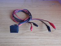
Attached picture shows the tool I made for sum/null by-ear tuning of passive crossovers. Wire is long enough to allow routing it through the ports of most vented speakers.
Attachments
I have an 600 watt RF amplifier here that uses an mechanical relay.
So I would believe that you really don't need to get into the vacuum relays etc.
Years ago I did a science fair project with my son where I took an off the
shelf remote A/B antenna switch and pulled out the coax relay and installed
a mechanical relay for a remote controlled light.
So you could probably do the same with off the shelf parts.
Note: I would not switch it Hot, amps are typically unhappy with being switched hot.
.
Last edited:
I have experienced long term problems when switching very low voltages and currents with common contacts rated for few amperes. In the short term it works. In the long term interaction between contact compounds and ambient chemistry creates an isolating coating, which requires some voltage to break down and some current to generate a small arc and vaporize.
I happen to be an amplifier designer too. I call "sparky" one of my quality control tests, it consists on playing tone bursts at about 1/3 to 1/10 full power, the load is a high power resistor bank with a series inductor of a few uH or dozen uH, and the high gauge leads of the load are rubbed against test binding posts to make it spark badly, at few dozen amperes peak or so. Any amplifier design that does not pass this test is not ready for release.
I happen to be an amplifier designer too. I call "sparky" one of my quality control tests, it consists on playing tone bursts at about 1/3 to 1/10 full power, the load is a high power resistor bank with a series inductor of a few uH or dozen uH, and the high gauge leads of the load are rubbed against test binding posts to make it spark badly, at few dozen amperes peak or so. Any amplifier design that does not pass this test is not ready for release.
- Status
- This old topic is closed. If you want to reopen this topic, contact a moderator using the "Report Post" button.
- Home
- Amplifiers
- Class D
- Proposed speaker polarity switch