Here i was talking about tweeter it self in no relation to amp discussion.If there is something that amp cant solve related to it then i will change tweeters design.
You can only exchange the tweeter against another with perfect electric behaviour. These tweeters do exist or more, there are some who come extremely close to that requirements, i.e. air motion transformers but you aren't talking about developing amplifiers there, you are talking about developing speakers.
So its impossible.Yes means that.And here i will not agree at all.
Well, since there's worldwide no solution applicable to such an amp to this point and you are that extremely confident, I assume you have serious research and development prowess at hand. What do they say to your concept?
At first place i didnt say that i will correct this with a "bit of feedback" but with complex science based design.
That's correct, you didn't say that. But it's neither possible to separate it without complex analyzing, probably not even realtime, neither is it possible to 'correct that bit only'. So, either what you meant, it's so far not possible. A simple feedback doesn't solve that problem. If it would, everyone on the market would do exactly such a simple method. Feedback is a huge topic, also here in the forum, why don't you look at some other threads and look what problems prevented them from having the perfect feedback compensation?
Simplifying things is good way to take fast and global look on what someone said....
I hate to say that but so far you're practically substituting 'simplifying' with 'ignoring' the problems.
I said that this is possible to be done (in real time with any impedance change) and now i will say that i will have that done after i finish what i am working on right now.
If you acocmplish that, I'll be the first to congratulate you and I honestly wish you best luck with that.
This is wrong interpretation of what i said.I said THE OPOSITE.Its possible to design AMP to work in autotune mode on any load change with zero phase shift on output....So amplifier will folow all whats on output and not the oposite.
I'm sorry, I'm not a native speaker and I cannot explain any better the problem you are not understanding. The autotune of speakerbox doesn't work actively/realtime, it works retrospectively and applies that. That does not have anything to do with realtime or actual compensation through feedback. I with you success with your amp concept.
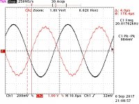
Here some real life measurements on a classD amp at 20kHz.
I am not convinced that the change of phase shift or group delay due to speaker impedance is really an issue for a reasonable classD amp with post filter feedback.
LiteAmp comes along with a group delay of approx 4us.
Measured on the gainboard (inverting voltage gain of approx. 4.9).
First screen shot is without load.
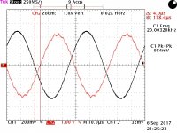
Second screen shot is with the Peerless 810921 tweeter.
(P.S.: Make sure to fire tweeters only short time with such power )
)
Measurement with x10 probe.
Vertical scale of input, Ch1: 2V/Div.
Vertical scale of output, Ch2: 10V/Div.
I am not convinced that the change of phase shift or group delay due to speaker impedance is really an issue for a reasonable classD amp with post filter feedback.
LiteAmp comes along with a group delay of approx 4us.
Measured on the gainboard (inverting voltage gain of approx. 4.9).
First screen shot is without load.
Second screen shot is with the Peerless 810921 tweeter.
(P.S.: Make sure to fire tweeters only short time with such power
)Measurement with x10 probe.
Vertical scale of input, Ch1: 2V/Div.
Vertical scale of output, Ch2: 10V/Div.
Attachments
@ ICG
"The autotune of speakerbox doesn't work actively/realtime" ...Friend we have missunderstanding here..... I said "Its possible to design AMP to work in autotune mode on any load change with zero phase shift on output". And word AMP is written with CAPS.I understand what you said about your english and its all fine.This discussion is about real life things and its not promotion of what i did or what i have done.So its all just positive.
I am doing this development my self,alone and i have no one to push me forward.....I love what i do and have no issues to work night and day for that love.I am playing with audio with first step i made in electronics in my life...And now when i think that i am enough skilled i decided to talk about all this and share what i know where as result i expect to better understand the philosophy of this kind of the design and have wider view of all the possibilities.
@Chocoholic
Smallest phase shift will be with smallest possible inductance and capacitance in output filter....this is going together with higher switching frequencies and injected THD together with that.Phase shift is important if you have voltage loop feedback....amp will not make proper correction to output with that feedback in time domain and distorsion will be higher on higher frequencies.Circuit that can in real time capture frequency and its phase shift will be capable to keep best correction and smallest distorsion on higher frequencies.Measurements you did are great thing for this thread.Thx
I am not convinced that the change of phase shift or group delay due to speaker impedance is really an issue for a reasonable classD amp with post filter feedback.
It wasn't about the phase itself, it was about correction of the response at different or changing impedances. If you change the impedance, you'll notice the phase differs a lot more. If you want to compensate for that and use a simple feedback, you'll feed back a phase error and that worsens the problem because of the phase/group delay.
LiteAmp comes along with a group delay of approx 4us.
Measured on the gainboard (inverting voltage gain of approx. 4.9).
First screen shot is without load.
Second screen shot is with the Peerless 810921 tweeter.
(P.S.: Make sure to fire tweeters only short time with such power
Well, how does it perform on impedance linear, impedance diving/capacitive tweeters? Or with drivers with rapidly changing impedance (like i.e. a horn)?What about the ripple you've got in? I assume you wouldn't say that's how it's supposed to be.
...Friend we have missunderstanding here.....
Yes, we undoubtetly do. I feel it doesn't lead to any conclusion anymore to discuss it further. We don't seem to understand each other, so it's maybe time to simulate the amp and discuss the result? I think it's probably easier to analyze and understand what's actually going on.
It wasn't about the phase itself, it was about correction of the response at different or changing impedances. If you change the impedance, you'll notice the phase differs a lot more. If you want to compensate for that and use a simple feedback, you'll feed back a phase error and that worsens the problem because of the phase/group delay.
Yup, such effects exist. Good or bad behavior of feedback will depend on the feedback.
For more insights it would be great if you could post three measurements:
1. A measurement which shows how / how much / how fast a certain real driver will change its impedance.
2. A measurement how / how much / how fast a certain amp will react on a fast well defined change of the load impedance (i.e. step of the load impedance).
3. A measurement which brings amp and speaker together, showing the resulting errors of the real life operation.
P.S.
The output ripple of course is a deviation vs ideal.
Since years unclear wheater this causes audible artefacts.
This is one good read for this topic https://hal.inria.fr/hal-01103665/document
Any delay/phase shift in speaker it self is absolutely NOT important for amp and has nothing with amp.There is a way to have this tracked in real time and if ever needed can be used for acoustics where speakers are.Speaker is inductive and voltage will lead phase over current....on capacitive ones its the oposite.....Amp need to care only for wave which is going out of the speaker to be without distorsion in relation to whats getting in to amplifier.
Speaker it self will change impedance for any frequency which is in its range ..... This can couse small phase change for each frequency thats going in to it.....Here i will agree.And i will not agree that feedback loop cant correct that.High quality D class designs will show very low thd on max power on speaker and not on linear load only....and all that in full freq. range......
I have here 2x18" 750W bass speakers,2x12" midrange 350W each and 2xBT250 (6kg - 250W each) tweeters (All speakers are Electrovoice ) .....I did many tests in last two days....Simple feedback loop can eliminate 99% of phase shifts coused with output filter or speaker it self on low and mid power.....on high power some more complex feedback is needed becouse currents through all capacitances are very high and some things will happen that should not.....even then with just little more work on feedback is possible to eliminate any phase shift.I will agree that phase shift can couse high thd on higher frequencies specially on higher output power....I mean here on frequencies above 5KHz.This can be avoided on two ways that i know....and i have this solved in my design.All this means very carefull designing and just that.
So far discussion is constructive but still we didnt define what we CANT do .....If we talk about real life amp is there anything that we cant make better?So far i achieved ultra low noise flor and low thd output ....protections are also nothing impossible to do......Only load independance is something that we didnt solve yet?
Speaker it self will change impedance for any frequency which is in its range ..... This can couse small phase change for each frequency thats going in to it.....Here i will agree.And i will not agree that feedback loop cant correct that.High quality D class designs will show very low thd on max power on speaker and not on linear load only....and all that in full freq. range......
I have here 2x18" 750W bass speakers,2x12" midrange 350W each and 2xBT250 (6kg - 250W each) tweeters (All speakers are Electrovoice ) .....I did many tests in last two days....Simple feedback loop can eliminate 99% of phase shifts coused with output filter or speaker it self on low and mid power.....on high power some more complex feedback is needed becouse currents through all capacitances are very high and some things will happen that should not.....even then with just little more work on feedback is possible to eliminate any phase shift.I will agree that phase shift can couse high thd on higher frequencies specially on higher output power....I mean here on frequencies above 5KHz.This can be avoided on two ways that i know....and i have this solved in my design.All this means very carefull designing and just that.
So far discussion is constructive but still we didnt define what we CANT do
.....If we talk about real life amp is there anything that we cant make better?So far i achieved ultra low noise flor and low thd output ....protections are also nothing impossible to do......Only load independance is something that we didnt solve yet?Yup, such effects exist. Good or bad behavior of feedback will depend on the feedback.
For more insights it would be great if you could post three measurements:
1. A measurement which shows how / how much / how fast a certain real driver will change its impedance.
2. A measurement how / how much / how fast a certain amp will react on a fast well defined change of the load impedance (i.e. step of the load impedance).
3. A measurement which brings amp and speaker together, showing the resulting errors of the real life operation.
P.S.
The output ripple of course is a deviation vs ideal.
Since years unclear wheater this causes audible artefacts.
Choco,
I think the measurements about your above mentioned points could be easily done with a comparison of a class-D with post filter with a nice class-AB amplifier as reference by taking its current waveform measurements alone. That will speak alot about pros and cons of both amplifiers as different topologies.
Last edited:
...not really, for the first measurement you will need voltage and current and from this one calculate the complex impedance. In order to get this fast one would need a cycle synchronized impedance calculation, then one could get the change of impedance over time. But also this method is limited to changes which are slow vs the period of the signal.
Furtheron the complex impedance can depend from various parameters, thermal heating or frequency.
Also measurement three is not so simple, because most likely the deviations will be small with real life impedance changes and one will need pretty much more resolution than standard scopes offer.
If you have a 12bit scope with huge memory on hand then we might have a chance to get it after we understood from measurement 1 and 2 what we are searching.
Comparably simple would be the second measurement.
Here a voltage measurement would be sufficient, because for the voltage we know how it should look. Only if we find that the amp acts like a perfect voltage source under worst conditions, then we could skip all other measurements, because if the amp is voltage source then the speaker will find ideal voltage drive. If all amps would be perfect voltage sources, then the speaker would act the same on all amps.
...but currently I don't even find the time for measurement 2...
BTW: Everybody is invited to show measurements.
What I actually meant was to co-relate the V and I measurements and this can eventually give us the idea about the deviation in impedance in dynamic way i.e plotting the very changing impedance with real world driving conditions but IMHO this should be done with both D and AB amps, its easy to evaluate the performance based on topologies as well.
Yupp, agreed.What I actually meant was to co-relate the V and I measurements ...
Now we only need a volunteer
As once someone said .... "Ohms law works just fine here" .....
Here is link for ,from my opinion, best ever speakers YouTube and this will bring us more to emotion repoduction and perfection.If you need more about these speakers search for omnidirectional speakers.
Here is link for ,from my opinion, best ever speakers YouTube and this will bring us more to emotion repoduction and perfection.If you need more about these speakers search for omnidirectional speakers.
Last edited:
Ultimate B.S.
Please share more with us and help us to see better what we dont see
.So far this is very helpful.Cheers,
- Status
- This old topic is closed. If you want to reopen this topic, contact a moderator using the "Report Post" button.
- Home
- Amplifiers
- Class D
- Ultimate D class amplifier design in theory.... :)