Hypex UCD400 OEM Amplifier & SMPS 400A400 Power Supply wiring questions
The Hypex Data Sheet for the UCD400 OEM and SMPS400A400 overall is pretty self-explanatory so far but still leaves me with a few questions. Especially when it comes to the connections for “SMPS Stand-by”, “Amp Stand-by “ and “Auto Amplifier Enable” on the SMPS400
Therefore it would be great to get some info and advise about some of the pin-outs and their wiring.
On the UCD400 OEM amp-module:
Pin32 Clipping detection output
Not necessary for basic amp operation, correct?
If applied, how and where to connect (resistor, LED network?)?
Pin33 DC Error Output
Not necessary for basic amp operation
If applied, needs to be connected to connector/pin J3.4 on the SMPS400A400
Or/alternatively
If applied, + positive side from speaker outs needs to be connected to the J6.1 and/or J6.3 on the SMPS, correct?
Pin34 ON/OFF Control Active Low
Necessary for basic amp operation otherwise the amp won’t leave the stand-buy mode.
Pin 34 needs to be connected via switch to ground to switch the amp active, correct?
Pin36 Current Limiter Monitoring
Not necessary for basic amp operation, correct?
If applied, how and where to connect?
On the SMPS400A400:
How/Where do I connect “SMPS Stand-by” (Connector J5.1 Input), “Amp Stand-by “(Connector J5.2 Input) and “Auto Amplifier Enable” (Connector J3.5 Output) ??
From the SMPS Data Sheet:
SMPS Stand-by
Applying an external DC voltage to this input will put the SMPS in standby. Both main and auxiliary output voltages will drop gradually. Removing the standby voltage will result in a normal soft started start-up of the SMPS400. Putting the SMPS in standby also automatically releases the Auto Amplifier Enable line guaranteeing pop-free shut down of the connected UcD amplifier.
Amp Standby
Applying an external DC voltage to the Amp Standby pin will put the amplifier in standby. The connected amplifier must be connected to Auto Amplifier Enable, described below, in order to use this option.
Auto Amplifier Enable
When the enable-line of a UcD/NCore series amplifier is connected to this pin, the amplifier will be enabled and disabled automatically when the SMPS400 is switched on and off. By doing so, it prevents unwanted audio artefacts during power cycles.
Any other tips and hints to get amp and PSU working to their full potential?
Many thanks in advance for any help
Last edited:
Wow, no one likes to share their (advanced) knowledge when connecting Hypex OEM model and smps ?
With the large numbers of Hypex OEM model sales on ebay at the moment it might be helpful for more than one person having all the information in one place
I've got the same problem when I was looking for a wiring diagram for 2x NC400 and SMPS 1200 A400. Could not get any response neither from Hypex nor from Hypex builders on this side. I did find one eventually somewhere on the net but I'm not 100% sure if it is correct. I don't think it would be valuable to you but it might give you some ideas so I can PM it to you if you like.
Wow, no one likes to share their (advanced) knowledge when connecting Hypex OEM model and smps ?
Just be patient, not everyone is reading this forum 24/7. Your question was just up there for 2 days.
Anyway, has Fenelaar answered your question? Do you need more assistance?
In order:
Pin 32 - not needed
Pin 33 - connect to SMPS J3.5
Pin 34 - connect to GND
Pin 36 - not needed
SMPS standby - leave disconnected
Amp standby - leave disconnected
Auto amplifier enable - connect to pin 33
Johan-Kr
Thank you very much for your help
You are stating "Pin 33 - connect to SMPS J3.5"
Pin 33 on the UCD400OEM is the DC Error Output and J3.5 on the smps400A400 is the Auto Amplifier Enable Output
Isn't it rather correct that Pin33 the DC Error Output on the module goes to J3.4 the DC-Error Input on the smps?
DC error output should naturally not be connected to Auto Amplifier Enable Output. They are both open collector outputs. AAEO is meant to enable the connected amp as soon as as all voltages of the SMPS are in range. DC error shuts down the SMPS in case of fatal failure of the amp.
DC error output should naturally not be connected to Auto Amplifier Enable Output. They are both open collector outputs. AAEO is meant to enable the connected amp as soon as as all voltages of the SMPS are in range. DC error shuts down the SMPS in case of fatal failure of the amp.
That's why I had this question to his answer.
The data sheets from smps and amp module stating clearly that Pin33 the DC Error Output on the module goes to J3.4 the DC-Error Input on the smps
I understand the basic connections to have the module working but I like the idea to use the stand-by function by applying an external voltage to the smps.
The smps data sheet states:
(This in conjunction with "SMPS Stand-By" and "Amp- Stand-By")
6.3 Auto Amplifier Enable (J3.5 Output)
When the enable-line of a UcD/NCore series amplifier is connected to this pin, the amplifier will be enabled and disabled automatically when the SMPS400 is switched on and off. By doing so, it prevents unwanted audio artefacts during power cycles.
Question: Where/Which pin is the enable-line on the UcD/NCore series amplifier that needs to be connected to Auto Amplifier Enable (J3.5 Output) on the smps?
I see no other options but (Input) PIN 34 on the UCD 400 OEM amp module. It's the pin that can be switched to ground otherwise to switch the amp on
Last edited:
Thank you. Here we goCorrect. PIN 34 is the enable line and should be switched to ground or pulled low bij de open collector output of the SMPS.
Is there a need to use a resistor while connecting pin 33 to J3:4?
The OEM manual (Ucd180_OEM_R4) says,
----------------------------------------------------------------------
The UcD180 (OEM version) has an integrated DC-error detection which will pull pin 33 low in case of such an event. It is recommended to sense this fault condition and to interrupt both power supply lines in such an event.
Item Min Typ Max Unit Notes
Voltage on pin 33, DC-error 1 V Internal open collector1)
Note 1: Must be pulled to a positive voltage by means of an external resistor. Open collector maximum output current: 100mA. Maximum collector voltage: 65V.
----------------------------------------------------------------------
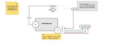
I have 4 Ucd180OEMs, pin 33 of all of them are interconected, and all these 4 UCD180OEMs share 1 SMPMS400A180.
I was advised by a person to use a resistor as shown in attachment.
[The system is automatically re-starting randomly. I was adviced that the instability is perhaps because I am not using a resistor as adviced in the manual]
Is this necessary?
The OEM manual (Ucd180_OEM_R4) says,
----------------------------------------------------------------------
The UcD180 (OEM version) has an integrated DC-error detection which will pull pin 33 low in case of such an event. It is recommended to sense this fault condition and to interrupt both power supply lines in such an event.
Item Min Typ Max Unit Notes
Voltage on pin 33, DC-error 1 V Internal open collector1)
Note 1: Must be pulled to a positive voltage by means of an external resistor. Open collector maximum output current: 100mA. Maximum collector voltage: 65V.
----------------------------------------------------------------------
I have 4 Ucd180OEMs, pin 33 of all of them are interconected, and all these 4 UCD180OEMs share 1 SMPMS400A180.
I was advised by a person to use a resistor as shown in attachment.
[The system is automatically re-starting randomly. I was adviced that the instability is perhaps because I am not using a resistor as adviced in the manual]
Is this necessary?
Attachments
Last edited:
Is there a need to use a resistor while connecting pin 33 to J3:4?
Is this necessary?
Yes, this is necessary, thats why it says "must". If you did not use the restistor and you have connected the the DC error output of the UcD180 OEM's directly to SMPS J3.1 you have probably destroyed your DC Outputs of the UcD's since you connected the HV Voltage directly to the open collector output. In an event of DC error, you will basicly short SMPS J3.1 to ground with no current limit, thus overloading the open collector output.
If you have not jet connected SMPS J3.1 directly to UcD J1.33, use a resitor to pull up to Vaux+. This probably solves the instabilty providing you did not directly connect SMPS J3.1 to UcD J1.33.
Last edited:
1. I have NOT connected SMPS J3.1 to UCD J1.33. (So no damage yet)
2. I have connected SMPS J3.4 to UCD J1.33 (without any resistor).
If I understood you correctly, you are saying
1. Connect SMPS J5.3 (Vaux +) to UCD J1.33 via a resistor (as shown in diagram)
2. Also connect SMPS J3.4 to UCD J1.33.
Thanks.
Is the resistor value of 22k correct? [4 UCDs are interconnected at pin 33]
")
Thx
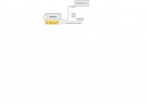
Yes. I am connecting DLCP J1:17 to pin J1:34 of each UCD OEM.
In addition to 4 UCD OEMs, I also use 2 UCD HGs. For these, I am taking DLCP J14:3 to the UCD_HG_1 J1:1, and J15:3 to UCD_HG_2 J1:1.
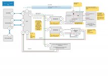
I have attached the diagram here. If it is correct, it may be of use to others as well.
Yes. I am connecting DLCP J1:17 to pin J1:34 of each UCD OEM.
In addition to 4 UCD OEMs, I also use 2 UCD HGs. For these, I am taking DLCP J14:3 to the UCD_HG_1 J1:1, and J15:3 to UCD_HG_2 J1:1.
I have attached the diagram here. If it is correct, it may be of use to others as well.
Attachments
Last edited:
@Antana, the issue was fixed.
The issue was a faulty cable between UCD HG 400 LS+ and SMPS400:J6:1. Replaced the cable, and the instability is gone.
Also added a resistor to handle dc_error of UCD OEM 180 modules basis your suggestion. Thanks!
Noticing two new problems. Posting here in case anyone has seen it before:
1. Loud pop when I shutdown the amp [ie, switch off using Remote --> switch of power supply], from the UCD HG modules. I thought amp_enable from DLCP:J14:3 to UCD HG:J1:1 would have handled it.
[Yes, connecting cables are OK]
2. Sometimes the volume control of Hypex Remote does not have any effect on volume. I can see the volume changing on Control panel display board, but the actual volume remains same. If I do a shutdown using Remote, I can see "Waiting for DLCP" in control board.
If I do switch off and switch on, volume works again.
Note: Wiring schematic in previous post
Thx
Attachments
Last edited:
- Status
- This old topic is closed. If you want to reopen this topic, contact a moderator using the "Report Post" button.
- Home
- Amplifiers
- Class D
- Hypex UCD400 OEM & SMPS 400A400 wiring questions