HI
i am back from holidays....
FauxFrench - your post at #303........ very impressive work..
Many thanks and welcome back. The TPA32XX discussions are less than half when you are away.
Don't worry, next summer holiday is almost a year away.

Many thanks and welcome back. The TPA32XX discussions are less than half when you are away.
Don't worry, next summer holiday is almost a year away.
thanks you for the roses...nice that your on board....

today i will try to get some measurements with the new coils and new caps on the output....but today i have my "wedding day"..............
")
hi
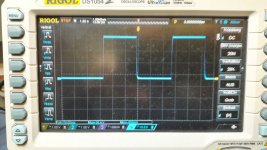
if you compare to page 29 post #286 to my modification on post #300....its looks better.
i am not an expert, and the laplace or Fourier transformations is too long time ago
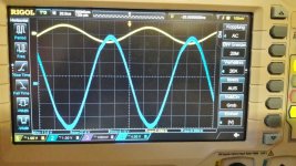
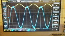
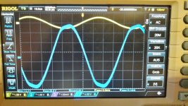
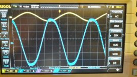
but its sounds better and on the scope i see the sinus more like a sinus = less harmonic thd....right?
chris
if you compare to page 29 post #286 to my modification on post #300....its looks better.
i am not an expert, and the laplace or Fourier transformations is too long time ago
but its sounds better and on the scope i see the sinus more like a sinus = less harmonic thd....right?
chris
Attachments
-
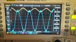 YJ_TPA3255_4ohm_7µH_1µF output filter_scope_6khz.jpg131.8 KB · Views: 789
 -
 YJ_TPA3255_4ohm_7µH_1µF output filter_scope_9khz.jpg130.4 KB · Views: 787
 -
 YJ_TPA3255_4ohm_7µH_1µF output filter_scope_13khz.jpg132.8 KB · Views: 774
 -
 YJ_TPA3255_4ohm_7µH_1µF output filter_scope_15khz.jpg129.9 KB · Views: 772
 -
 YJ_TPA3255_4ohm_7µH_1µF output filter_scope_19khz.jpg133.9 KB · Views: 771
Congratulations with your wedding day! Do not make my mistake and forget it occasionally (result ).
You work thoroughly on the power part. I did some analysis on the input part like many other. Perhaps one day the manufacturer may read about our efforts and improve some of our concerns. It need not be costly in manufacturing.
).You work thoroughly on the power part. I did some analysis on the input part like many other. Perhaps one day the manufacturer may read about our efforts and improve some of our concerns. It need not be costly in manufacturing.
hi
if you compare to page 29 post #286 to my modification on post #300....its looks better.
i am not an expert, and the laplace or Fourier transformations is too long time ago
but its sounds better and on the scope i see the sinus more like a sinus = less harmonic thd....right?
chris
sorry.......... this statement is not fair = correct.
measuremnts on page 29 is 8 ohms load
and now it is the optimized 4ohms output filter with 4 ohms load
i will recheck and show
Hi Abraxalito
AAAh...fine this is exactly my board where i am try something.
According to your answer...you tried the cap on AVDD.
i have 4 boards 2 payed at amazon/nobsound and the other 2 i got because i claimed amazon about the 50V at LM2575S--> so i get 2 for free
now the technical datas are changed to 40V....
other things what you recommend to do?
here is my suggesetion:
1
input caps 6x 10µ/16V (actually a changed the 2 at the audio path with bi polar muse (my last onces
2
bulk caps i tried original (elna or samwha), or nichicon 3300 UFG serie, or nichicon UHE series - in my volume no difference
3
change the LM317 coil wrong 220=22µH to 221= 220µ H
4
change the caps near the LM317 + LM2575S to 220µf - 16YXM220MEFC8X11.5
5
change the output on LM2575 on 2 boards, 1 is still at 12,75V, 1 is completle original
6
avoid short by the heatsink on smd components (is corrected in later versions)
not done:
7
change opamp
8
change
10k smd at opamp to 1% or better tolerance
9 other LC output filter
my DAC is Gustard A20H -cable viablue nf -S6 Silver RCA
thank you...
chris

...pump it up...Abraxalito?
smps test meanwell ..
Hi
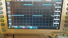
after a hard office working week i am back with some measurments. i read in other thread about the smps and so i start a short test for the Meanwell LRS 350-36 and LRS150-24 which i plan to use for my prototype amps.
i want to see the hickup mode and which load is pushing or not.
as i learned from doctor and other here in the forum..with about 12mF or more the hickup mode will not been solved.
first i my pdf with my measurements
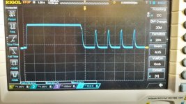
pic 1 LRS350-36 with 2,6ohms load - hickup without caps
pic 2 LRS350-36 with 2,6 ohms load- hickup12mF caps
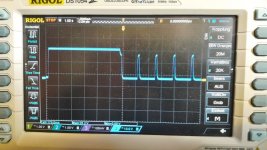
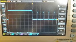
pic 3 LRS150-24 with 2,6ohms load - hickup without caps
pic 4 LRS150-24 with 2,6ohms load - hickup 12mF caps
pic 5 LRS150-24 with 2,6ohms load - hickup 33mF caps
chris
Hi
after a hard office working week i am back with some measurments. i read in other thread about the smps and so i start a short test for the Meanwell LRS 350-36 and LRS150-24 which i plan to use for my prototype amps.
i want to see the hickup mode and which load is pushing or not.
as i learned from doctor and other here in the forum..with about 12mF or more the hickup mode will not been solved.
first i my pdf with my measurements
pic 1 LRS350-36 with 2,6ohms load - hickup without caps
pic 2 LRS350-36 with 2,6 ohms load- hickup12mF caps
pic 3 LRS150-24 with 2,6ohms load - hickup without caps
pic 4 LRS150-24 with 2,6ohms load - hickup 12mF caps
pic 5 LRS150-24 with 2,6ohms load - hickup 33mF caps
chris
Attachments
-
 LRS150_24_33mF_2ohms_Hickup.jpg121.5 KB · Views: 91
 -
 LRS150_24_12mF_2ohms_Hickup.jpg116 KB · Views: 92
 -
 LRS150_24_nocaps_2ohms_Hickup.jpg117.5 KB · Views: 94
 -
 LRS350_36_12mF_2ohms_Hickup.jpg113 KB · Views: 109
 -
 LRS350_36_no caps_2ohms_Hickup.jpg117.8 KB · Views: 109
 -
SMPS_Meanwell tests.pdf392.9 KB · Views: 84
Amp light
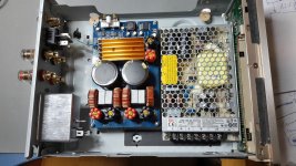
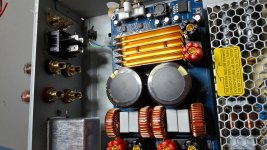
my first protoype will be a small amp in a litte nice housing.
the "AMP light"
i will use:
YJ TPA board (after SQ test i will decide which one...here its the original) configuration is for 4 ohm speakers
LRS150-24V because of the limited room in the housing
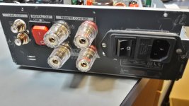
1 pair RCA connectors
1 power switch with fuse and filter (its the version for a bigger amp but...)
2 pairs of output connectors
1 mute switch for power on/off..actually i haven´t realised doctores mute circuit
cu
chris
my first protoype will be a small amp in a litte nice housing.
the "AMP light"
i will use:
YJ TPA board (after SQ test i will decide which one...here its the original) configuration is for 4 ohm speakers
LRS150-24V because of the limited room in the housing
1 pair RCA connectors
1 power switch with fuse and filter (its the version for a bigger amp but...)
2 pairs of output connectors
1 mute switch for power on/off..actually i haven´t realised doctores mute circuit
cu
chris
Attachments
Dear Doctormord,
I saw on your website that you were using Codaca inductor, with a similar shape to the Wurth inductors highlighted in TI LC filter design paper.
Maybe difficult to answer, but do you expect those Codaca inductors to result in similar performances to the Wurth ones (not too far away) ?
If not secret, what are the exact ref that you used (they have a quite packed catalog for high current inductors I those values) ?
Best regards,
JMF
Oups, I found my answers in the "correct thread:
TPA3255 - all about DIY, Discussion, Design etc.
Ref seems to be CSCF2014-6R8M
Sorry for the intrusion here
JMF
TPA3255 - all about DIY, Discussion, Design etc.
Ref seems to be CSCF2014-6R8M
Sorry for the intrusion here
JMF
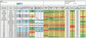
as it expected, the best inductor has more turns and the bigger gap that makes saturation current about 22A. The drawback is higher Rdc but that not a big problem at all. Material #2 inductors have a good linearity as well, however, their magnetic field is almost not shielded and will affect S/N and THD again.
Ref seems to be CSCF2014-6R8M
They're basicly the same as the more expensive Wurth inductors. An alternative are FerroCore HCI2114-7R0.
output filter
Hi
i want to simulated in the TI Designer for Output filter the difference of my 2 boards for 4 ohms load.
1 board is as recommended by TI 7µH + 1µF
2 board is like the TPA3251EVM 7µ +0,68µF
what should i configure at the input? hybrid, BTL...???
SQ is different between the 2 boards. As expected the board 2 (0,68µf) is slightly smoother in the high.
thx
chris
my first protoype will be a small amp in a litte nice housing.
the "AMP light"
cu
chris
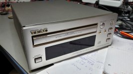
It looks really good, Chris.
Reuse of a cabinet is possible.
Chris,
for the TPA3251EVM (and the TAS3251EVM), it is "common mode" in the Class-D LC filter excel sheet.
JMF
thx
- Home
- Amplifiers
- Class D
- What is wrong with TPA3255?