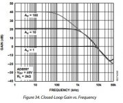
AD8599 does not have enough GBW to offer linear gain in the audio band up to 20kHz for gain <= 1. Not even usefull as a buffer.
See datasheet P.11 Fig34/37
oh...really? because at the graph the x-axis is written frequency (khz) so 1khz means 1k *k = 100khz.............????
typo?.. in the datasheet or really a gain up to 10khz and then hard rolloff ?
Attachments
Last edited:
My fault, you're right.
Btw. may i suggest to get a used "Emu Tracker Pre" + Arta for measurements? Makes everything much easier.
You just need to build a simple attentuator for power measurements and you're set.
We have some infos here for using it:
Stromrichter - Messtechnik
Btw. may i suggest to get a used "Emu Tracker Pre" + Arta for measurements? Makes everything much easier.
You just need to build a simple attentuator for power measurements and you're set.
We have some infos here for using it:
Stromrichter - Messtechnik
My fault, you're right.
Btw. may i suggest to get a used "Emu Tracker Pre" + Arta for measurements? Makes everything much easier.
You just need to build a simple attentuator for power measurements and you're set.
We have some infos here for using it:
Stromrichter - Messtechnik
yeah...you can read my brain

yesterday i try with my scope the FFT measurement.....
this could be the next step..
thank you!!
Have you measured the opamp outputs?
(Before/after the interstage coupling caps, so you can see if it comes from the opamps or the amplifier itself)
hi doc
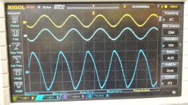
i made the measurements:
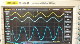
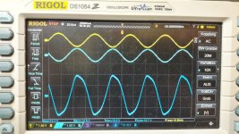
8 ohms load, 400mVrms input
yellow - top curve is input at RCA R channel
blue - opamp pin 7 at TL072 or pin4 inverted
dark blue differential probe at output of the amp
pic1 6khz - here is the deformation starting
pic2 17khz- pin 7 at the opamp
pic3 17khz pin 4 inverted output
pic4 20khz clear deformation
so it comes from amp/output filter..i try to search for a point after the amp before the output filter...not easy...my suggestion is without heatsing on the output pins of the TPA...right??
Attachments
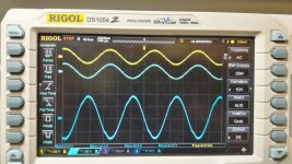
pic1 6khz - here is the deformation starting
pic2 17khz- pin 7 at the opamp
pic3 17khz pin 4 inverted output
pic4 20khz clear deformation
I don’t understand.
looking at the scopeplots I see output levels of approx +-15V, i.e. you are pushing TL072 hard into the limits. The deformation might be overload recovery time. In that case deformation increases visible with frequency.
Normally I would not consider such levels being necessary to drive the input of any class-d-amp.
btw, pin4 of TL072 is Vee.
Normally I would not consider such levels being necessary to drive the input of any class-d-amp.
btw, pin4 of TL072 is Vee.
I don’t understand.
Hi doc
hi Voltwide
i try again..i see the deformation = no nice sinus wave at the speakers output--->
sinus wave on the scope display: from top to buttom
1
yellow is the rca input with the frequency generator 400mVrms measured at the RCA input socket
2
the line below is on the opamp pin 7 or pin 1 (not 4) output of the opamp to check if its here the problem with the "strange wave form" ...no its not
i try pin 7 and pin 1 to look if there is mybe a problem with the other output
@ voltwide its not + - 15V on the output of the opamp
...this is the last curve on the display its the output socket-->33
output on the speaker socket measured with differential probe
is it now clearer?...sorry if i was not clear.
i really appriciate for your time to help me.....
measurements 4ohm and 8ohm
Measurments with 31V PSU , input 400mVrms, 4 ohms or 8 ohms resistive load each channel.
4 YJ boards:
original +
amp1+2 modified boards (LM317, LM2575 + input caps, bulk caps) ,
amp3 modified board ( LM317 at 12,75 V.., LM2575 +input caps, bulk caps,)
TPA3251EVM
VPP with differential probe at output speakers terminal
Attachments
Last edited:
Hi
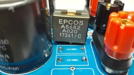
Anybody tried different coils on the YJ board? execpt Sybic
i am thinking about to use better coils = shielded but the room for the LC filter is limited on this board.
my idea is to mount the output caps under the pcb to get more space for the 4 coils in BTL mode....eg.
VER2923-103KL Colicraft
7443631000 Würth
any suggestions?
Attachments
Last edited:
Hi developers and experts
i found in this thread:
DIY TPA3244 board
#7 - a comment
Its this AVDD rail (brought out for decoupling at pin9) which is the crucial one. I found a 1000uF/16V Nichicon HZ to make a considerable improvement to clarity when hung on the equivalent rail of the TPA3255.
original its written in the datahsett 1µF and on the board I can see a 1µF smd cap too.
has somebody try this extra cap??
pump it...
If it would be needed, it would be part of the EVM. Abraxalito didn't told what board he got his hands on.
I never felt like i'd miss some "clarity" on all class-d amps i built so far.
thanks
doctor ..please have you time to go back to my measurments? and clarify...
i really appreciate you help
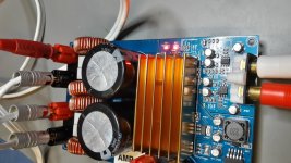
Still waiting for PCB pics.
Regarding your measurements.. have you scoped PVDD at the caps as well?
Actually i don't know whats going on there. I would desolder the filter inductors and try some flatwire ones which can handle the current to see if it affects the waveform. Do the filter foilcaps get warm/hot?
Regarding your measurements.. have you scoped PVDD at the caps as well?
Actually i don't know whats going on there. I would desolder the filter inductors and try some flatwire ones which can handle the current to see if it affects the waveform. Do the filter foilcaps get warm/hot?
Still waiting for PCB pics.
Regarding your measurements.. have you scoped PVDD at the caps as well?
Actually i don't know whats going on there. I would desolder the filter inductors and try some flatwire ones which can handle the current to see if it affects the waveform. Do the filter foilcaps get warm/hot?
pics are in the fx502spro thread...but not able to view the layer.please reda there..
no measurement at PVDD
...do you mean the big one or the smal grey at the output?new coils are ordered
--> tasks before my holiday
thank you!
If it would be needed, it would be part of the EVM.
The EVM didn't get designed for SQ. Its certainly not needed to deliver the DS numbers.
I am fairly sure I did mention its the Taobao one found here : YJ00312-TPA3255??????300W+300W)-???Abraxalito didn't told what board he got his hands on.
What DAC do you use to drive them?I never felt like i'd miss some "clarity" on all class-d amps i built so far.
The EVM didn't get designed for SQ. Its certainly not needed to deliver the DS numbers.
I am fairly sure I did mention its the Taobao one found here : YJ00312-TPA3255??????300W+300W)-???
What DAC do you use to drive them?
Hi Abraxalito
AAAh...fine this is exactly my board where i am try something.
According to your answer...you tried the cap on AVDD.
i have 4 boards 2 payed at amazon/nobsound and the other 2 i got because i claimed amazon about the 50V at LM2575S--> so i get 2 for free

now the technical datas are changed to 40V....
other things what you recommend to do?
here is my suggesetion:
1
input caps 6x 10µ/16V (actually a changed the 2 at the audio path with bi polar muse (my last onces
- i like the muse 2
bulk caps i tried original (elna or samwha), or nichicon 3300 UFG serie, or nichicon UHE series - in my volume no difference
3
change the LM317 coil wrong 220=22µH to 221= 220µ H
4
change the caps near the LM317 + LM2575S to 220µf - 16YXM220MEFC8X11.5
5
change the output on LM2575 on 2 boards, 1 is still at 12,75V, 1 is completle original
6
avoid short by the heatsink on smd components (is corrected in later versions)
not done:
7
change opamp
8
change
10k smd at opamp to 1% or better tolerance
9 other LC output filter
my DAC is Gustard A20H -cable viablue nf -S6 Silver RCA
thank you...
chris
Last edited:
....
Actually i don't know whats going on there. I would desolder the filter inductors and try some flatwire ones which can handle the current to see if it affects the waveform. Do the filter foilcaps get warm/hot?
after my temp test not really gettting hot...they are not fixed with a glue or something
new attachment

neverthless i plan some new coils in respect of the dimension of the board and the precondition output foil caps mounted under the pcb.
Attachments
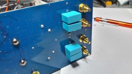
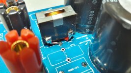
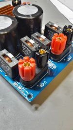
...9 other LC output filter...done..
its nice to get a package from digikey 4 days later...
i decided to configure the board as TI mentioned for 4 ohms = 7µH + 1µF
as i planned.......... the coils are strange to mount
TDK caps 1µF under the pcb
sound check will follow....
its nice to get a package from digikey 4 days later...
i decided to configure the board as TI mentioned for 4 ohms = 7µH + 1µF
as i planned.......... the coils are strange to mount
TDK caps 1µF under the pcb
sound check will follow....
Attachments
- Home
- Amplifiers
- Class D
- What is wrong with TPA3255?