The supply is capable of providing more current for short demands, OC trip is at 140% if remeber correctly. (Depending on duration)
as usual...you are right
") ...i checked the datasheet...overload 100%- 140%
...i checked the datasheet...overload 100%- 140%Hello,
I need your advice ...
1. Is it possible to use this amp version with 8 ohm load and 51-52 V DC supply ?? ( when LM2575 is replaced to HVS version .... ) ...
2. Is it a bad idea to use external heatsink mounted on the amp case and connected to TPA3255 top termal pad ??? ( any problems with that idea ??? ) .
Best regards,
Emil
Hi emil
please take into account the same topic which is mentoined by Doctor. The overshoot of the psu. the LM2575HV its max is 60V. so if you have a psu with 53V (you wrote me...) and an expected and guarenteed overload of 110%-140% with an + - 1% over voltage you get:
53V +5,3V = 58,3V ...so its neraly to the boarder of the LM2575HV.
chris
edit: i add the graph...attached
Attachments
Last edited:
In my opinion the LM2575 and LM2575HV are both made from the same silicon. To my knowledge, they test them at the fab with overvoltage to "predegrade" the circuit and measure the leakage current afterwards. If it is higher than specified for the HV version they put them into the "normal" specification test. If it fits then, you'll get an LM2575. If leakage is low enough to fit the HV needs, they sell/mark em like so. This is common practice for a lot of different devices at all vendors.
Anyway your considerations are correct.
Anyway your considerations are correct.
..power measurement...switch off....
Hi again
i checked with DMM the OCP configuration and it is 21,75 k ohm so it is near the recommended 22kR = 17A OCP
i cheked the KEF Q100 its rated official as 8 ohm speaker but i found some impedance cureve about 4 ohms...so some results say 4 ohm speaker. i xchecked mine. its sticker is 8 ohm but i measured with my DCR 3,60 ohm.. so i say 4 ohm speaker
scope measurments with differential probe (testec TT-SI 9002...@20X):
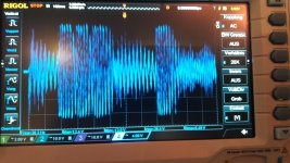
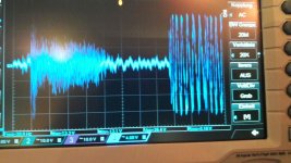
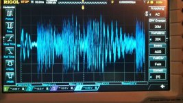
music title 41 sec at Desiigner - PANDA =switch off
pic 1 the shot of switch off...29,4Vpp
pic 2 +3 are shot about 26,4Vpp
so the amp is switching off...so if i take 4R speakers how to calculate the power?
Ppeak= Vpeak^2 / 2*R
Ppeak=29,4^2 / 2 *4
Ppeak= 55,5 WATT per channel
correct?
for loud volume without switch off:
Ppeak=26,4^2 / 16
Ppeak= 43,5 Watt peak per channel
why switch off.....strange for me?
Hi again
i checked with DMM the OCP configuration and it is 21,75 k ohm so it is near the recommended 22kR = 17A OCP
i cheked the KEF Q100 its rated official as 8 ohm speaker but i found some impedance cureve about 4 ohms...so some results say 4 ohm speaker. i xchecked mine. its sticker is 8 ohm but i measured with my DCR 3,60 ohm.. so i say 4 ohm speaker
scope measurments with differential probe (testec TT-SI 9002...@20X):
music title 41 sec at Desiigner - PANDA =switch off
pic 1 the shot of switch off...29,4Vpp
pic 2 +3 are shot about 26,4Vpp
so the amp is switching off...so if i take 4R speakers how to calculate the power?
Ppeak= Vpeak^2 / 2*R
Ppeak=29,4^2 / 2 *4
Ppeak= 55,5 WATT per channel
correct?
for loud volume without switch off:
Ppeak=26,4^2 / 16
Ppeak= 43,5 Watt peak per channel
why switch off.....strange for me?
Attachments
..switch off solved
Hi
i look at the 3rd board and i want to look at the chip and therefore i see the different of the heat sink. i pick the heat sink and put it on amp one and i made the loud volume test again. so.... it was really loud and no switch off.
so in my suggestion the original old version of the board shorted something with the heat sink!!!!
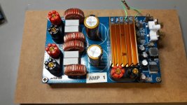
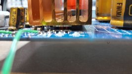
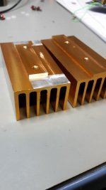
pic 1 different heat sink old and new(cutted area)
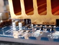
pic 2 old heat sink -shortcut of smd components
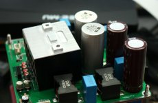
pic 3 new heat sink final mounted
pic 4 measurement with scope differential
pic 5 amp mounted- so do I to listened to music
chris
Hi
i look at the 3rd board and i want to look at the chip and therefore i see the different of the heat sink. i pick the heat sink and put it on amp one and i made the loud volume test again. so.... it was really loud and no switch off.
so in my suggestion the original old version of the board shorted something with the heat sink!!!!
pic 1 different heat sink old and new(cutted area)
pic 2 old heat sink -shortcut of smd components
pic 3 new heat sink final mounted
pic 4 measurement with scope differential
pic 5 amp mounted- so do I to listened to music
chris
Attachments
Last edited:
Proper heatsinking is like so:

Polished or milled down with small amount of thermal grease and some "downforce".
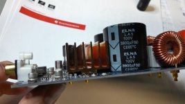
fantastic board. heat sink handmade? or better hand made with your cnc machine??
the caps (GPD) i noted last week - i really like it


Finally fixed the values and made some DIY-friendly instructions for the Automute/Pop-On/Pop-off/Powerdown thingie:
http://www.diyaudio.com/forums/class-d/287470-tpa3255-diy-discussion-design-etc-73.html#post5488402
http://www.diyaudio.com/forums/class-d/287470-tpa3255-diy-discussion-design-etc-73.html#post5488402

Hi developers and experts
i found in this thread:
DIY TPA3244 board
#7 - a comment
Its this AVDD rail (brought out for decoupling at pin9) which is the crucial one. I found a 1000uF/16V Nichicon HZ to make a considerable improvement to clarity when hung on the equivalent rail of the TPA3255.
original its written in the datahsett 1µF and on the board I can see a 1µF smd cap too.
has somebody try this extra cap??
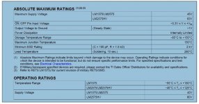
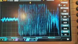
...strange waveform...
i got strange waveform at the outputs.now i have a differential probe and its the same. any hints to perform better mesurement methods?
especially irrebo and doctor warnt me that wihtout differential probe my measurements are wrong.
As testet in the TPA3250 thread- FX502Spro #608
TPA3250 somebody is listening?
now....i tested all my YJ boards:
i get nearly the same sinus wave form as in #593 in the same thread.
only my very silent and superior playing TPA3251EVM board shows just small "deformation" at 20k and above.
my suggestion is that here is a topic of EMV issus at the chinese implementation??? some hints to make it better?
does it help with other coils and caps at the output filter?
thanks in advance
chris
Have you measured the opamp outputs?
(Before/after the interstage coupling caps, so you can see if it comes from the opamps or the amplifier itself)
Hi Doctor
i measured the frequency responce of all of my boards (4x YJ = 3mod 1 original +TPA3251EVM) @ 4 ohms load and 400mV input 1khz. today eveneing i plan to do with 8ohm load.
no ...no measurements at the opamps (at the FX502SPRO i did). hopefully not from the opamps. my new SMD desoldering/soldering equipment is delivered hopefully tomorrow.
sorry for the nooby question...can i measure without diff scope probe at the inputs of tpa chip?
ok....i will do that. I really appriciate your help.
No need to desolder anything, just probe to see whats coming out of the opamps.
Probing without diff-probe is fine, just get the correct AGND reference.
thx a lot
btw...desoldering is for modding in general......YJ => the opams tL072 --> AD8599 or equal
- Home
- Amplifiers
- Class D
- What is wrong with TPA3255?