many thanks FF
cant find section 8,2.2.10.......?
http://www.ti.com/lit/ds/symlink/lm2575.pdf
Page 11 at the bottom. Continues on page 12.
http://www.ti.com/lit/ds/symlink/lm2575.pdf
Page 11 at the bottom. Continues on page 12.
thanks
i had opened always a version from 2013? this is not ordered in chapters.... directly from google search...strange
thx
Hi Chris,
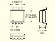
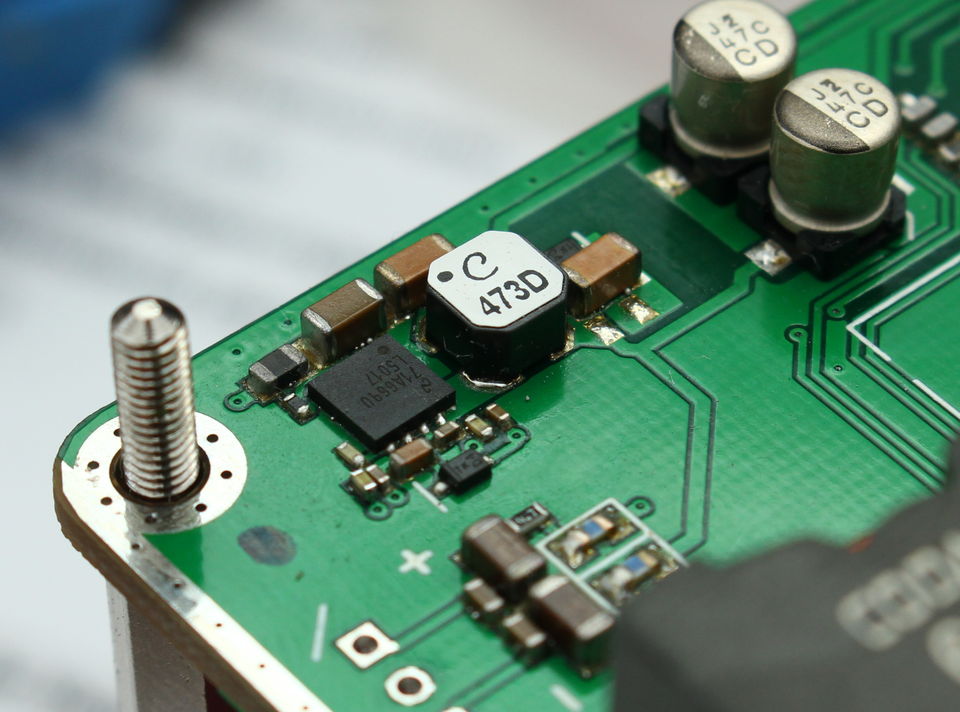
I see small white dot marker on the board the beside the pin of op amp.. that pin is pin 1?
yes
8 7 6 5
o
1 2 3 4
Attachments
This solution does not take too much board space and works reasonably well in my TPA325x designs.
Correct, the complete LM5017 implementation takes roughly same/less space than the LM2575 IC case alone. Dunno why they don't use it...

I have all parts sitting on my work bench. Just need to find some spare time.
Yes, on reflection US$50 is quite pricey for that regulator, especially compared to the price of the Chinese TPA3255 boards.
For my own TPA3250 build I will use a TPS7A4700 regulator (from ldovr) with its own transformer, to power the 12V rail. I will be bypassing the input opamps, so I don't need 15V.
regulator
what about this...nonsense?
TPS7A4700 Low Noise Power Module DC DC 3 36V to 3V 3.3V 5V 12V 15V 1A Adjustable AUG_25 Dropship-in Acoustic Components from Electronic Components & Supplies on Aliexpress.com | Alibaba Group
It is probably a fine regulator. But, it is a linear LDO with the same power loss as other linear regulators and in this layout little possibility to get rid of the heat. LDOs are often meant as post-regulators with little voltage difference from input to output. For TPA3255 use, you may need more than 100mA from the 12V rail. Therefore, you will need an input voltage that is only a few volts higher than the 12V output (not to have heating problems). If you have that (using the LM2575) the question is if you can actually hear the difference from the initial LM317.
It is probably a fine regulator. But, it is a linear LDO with the same power loss as other linear regulators and in this layout little possibility to get rid of the heat. LDOs are often meant as post-regulators with little voltage difference from input to output. For TPA3255 use, you may need more than 100mA from the 12V rail. Therefore, you will need an input voltage that is only a few volts higher than the 12V output (not to have heating problems). If you have that (using the LM2575) the question is if you can actually hear the difference from the initial LM317.
ok. thanks...
so as i read the LDO are mostly use for small equipment DAC..etc. to get from 5 to 3.3V regulator...etc..
i have 2 boards left with the LM2575S-15 + LM317 config - version 1
and the other boards are with the LM2575T-12 config -version 2
so the version 1 seems to be the better solution.
finally i think about splitting the rails...opamp - -- TPA voltages
Last edited:
ok. thanks...
so as i read the LDO are mostly use for small equipment DAC..etc. to get from 5 to 3.3V regulator...etc..
i have 2 boards left with the LM2575S-15 + LM317 config - version 1
and the other boards are with the LM2575T-12 config -version 2
so the version 1 seems to be the better solution.
finally i think about splitting the rails...opamp - -- TPA voltages
A quite good solution would be to use an LM2575S-15 to step the initial input voltage down to 15V with little loss and two linear post regulators to supply 12V for the TPA3255 (one post regulator) and 12V for the OP-AMPs (the other post regulator). Then, there is little disturbance on the OP-AMPs from the TPA3255 digital consumption. The problem is if you can split the 12V power rail in an existing board.
Alternatively, use the SMPS output (12V) directly for the TPA3255. Make a linear regulator straight from the raw input voltage for the OP-AMPs. Then you can have an 18V or 24V supply for the OP-AMPs and lower THD.
A last, perhaps controversial, view: Modern LDOs appear very attractive at first view - low voltage drop (and power loss) and often magificent noise specs.
If you can take advantage of that low voltage drop depends on what is your input voltage and output voltage. If you anyway have 3V or more, the LDO provides no benefit.
Another argument relates to the dynamic output swing at an LDO. The magnificent noise figures are with an absolutely steady load. Such is found in certain measurement circuit and low noise may be essential. For most audio circuits the loading is not stable but varies with the audio signal. An LDO has a collector output (current source) such that any change in the loading needs the regulation loop to react importantly. This causes the output voltage to swing until the new balance is found. The very nice noise figure appears rather futile.
The "old" (traditional) voltage regulators use traditionally an emitter output. An emitter output is inherently low impedance and the regulator loop needs to react very little to changes in the loading. I would not be surprised if a traditional regulator performs better than an LDO in the same audio circuit.
An SMPS with a linear post-regulator normally performs better stability and noise wise than only an SMPS.
Last edited:
A quite good solution would be to use an LM2575S-15 to step the initial input voltage down to 15V with little loss and two linear post regulators to supply 12V for the TPA3255 (one post regulator) and 12V for the OP-AMPs (the other post regulator). Then, there is little disturbance on the OP-AMPs from the TPA3255 digital consumption. The problem is if you can split the 12V power rail in an existing board.
Alternatively, use the SMPS output (12V) directly for the TPA3255. Make a linear regulator straight from the raw input voltage for the OP-AMPs. Then you can have an 18V or 24V supply for the OP-AMPs and lower THD.
A last, perhaps controversial, view: Modern LDOs appear very attractive at first view - low voltage drop (and power loss) and often magificent noise specs.
If you can take advantage of that low voltage drop depends on what is your input voltage and output voltage. If you anyway have 3V or more, the LDO provides no benefit.
Another argument relates to the dynamic output swing at an LDO. The magnificent noise figures are with an absolutely steady load. Such is found in certain measurement circuit and low noise may be essential. For most audio circuits the loading is not stable but varies with the audio signal. An LDO has a collector output (current source) such that any change in the loading needs the regulation loop to react importantly. This causes the output voltage to swing until the new balance is found. The very nice noise figure appears rather futile.
The "old" (traditional) voltage regulators use traditionally an emitter output. An emitter output is inherently low impedance and the regulator loop needs to react very little to changes in the loading. I would not be surprised if a traditional regulator performs better than an LDO in the same audio circuit.
An SMPS with a linear post-regulator normally performs better stability and noise wise than only an SMPS.
....hmmm ....its so long time ago....I have to read this twice but i think i understand your comments....
thank you
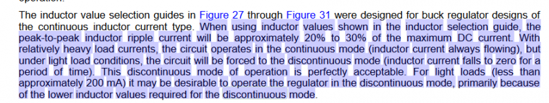
i checked the pics of post 540. i read the datasheet and there is written something about discontinuous mode and the graphs shows exactly the same.
so i understand that the smaller inductance is because of the peak current and you have to calculate more power I * 1,3 and therefore a value with less inductance.
pic 1
correct?
i found a chapter in LM2596 (its the same chip but quicker 150khz)
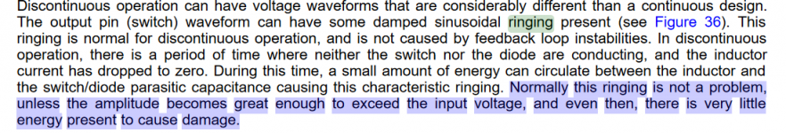
that ringing is a problem if the voltage exceed the input voltage
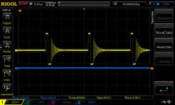
pic 2
i use 28V psu = input of the regulator LM2575T-12 and the ringing at pic 3 (#post 540) is 29,6V. ...correct?....
so i understand that the smaller inductance is because of the peak current and you have to calculate more power I * 1,3 and therefore a value with less inductance.
pic 1
correct?
i found a chapter in LM2596 (its the same chip but quicker 150khz)
that ringing is a problem if the voltage exceed the input voltage
pic 2
i use 28V psu = input of the regulator LM2575T-12 and the ringing at pic 3 (#post 540) is 29,6V. ...correct?....
Attachments
Hi experts
i found this at the Data sheet - chapter 10.1.2.2 Cout -ripple...
Low ESR for COUT is desirable for low output ripple. However, the ESR should be greater than 0.05 Ω to avoid the possibility of regulator instability. Hence, a sole tantalum capacitor used for COUT is most susceptible to this occurrence.
some experience?
no
You observe this kind of ringing in dscontinuous mode of a buck regulator with clamp diode. This occures at light load, when ripple current is bigger than load current. This is not harmful per se, in most cases this will not produce audible interference.
To avoid discontinuous mode at low load you can do
-increase inductance
-increase pwm frequency
-reduce input voltage
This mode does not occur when using a synchronous rectification buck regulator (syncbuck).
no
You observe this kind of ringing in dscontinuous mode of a buck regulator with clamp diode. This occures at light load, when ripple current is bigger than load current. This is not harmful per se, in most cases this will not produce audible interference.
To avoid discontinuous mode at low load you can do
-increase inductance
-increase pwm frequency
-reduce input voltage
This mode does not occur when using a synchronous rectification buck regulator (syncbuck).
Hi Voltwide
thank you that you take time to answer my noob questions.
so this grapsh shows that the regulator is indisc. mode = that menas that according to the datasheet the current is less then 200mA?
Correct?
it was audible...its was the clipping led which makes me nervous...
synbuck ???for 28Vin and 12V out....example please
thank you
catch diode...schottky or not...
sorry to boring you experts....but...
according to the datasheet.
10.1.2.3
If a high-efficiency, fastrecovery, or ultra-fast-recovery diode is used in place of a Schottky, it should have a soft recovery (versus abruptturn-off characteristics) to avoid the chance of causing instability and EMI.
why is written more then once that a fast recovery diode is recommenden.???!
e.g.
page 17/ point 4
table 1
i am confused...
You may ignore this hint. Fast soft recovery is an issue with off-line flyback converters, not with SELV voltage bucks.sorry to boring you experts....but...
according to the datasheet.
10.1.2.3
If a high-efficiency, fastrecovery, or ultra-fast-recovery diode is used in place of a Schottky, it should have a soft recovery (versus abruptturn-off characteristics) to avoid the chance of causing instability and EMI.
why is written more then once that a fast recovery diode is recommenden.???!
e.g.
page 17/ point 4
table 1
i am confused...
Hi Voltwide
thank you that you take time to answer my noob questions.
so this grapsh shows that the regulator is indisc. mode = that menas that according to the datasheet the current is less then 200mA?
Correct?
it was audible...its was the clipping led which makes me nervous...
synbuck ???for 28Vin and 12V out....example please
thank you
LM5017 (100V input) - and there exist cheaper ones for less input voltage.
Have a look at parametric search (mouser, digikey...) to find them.

- Home
- Amplifiers
- Class D
- What is wrong with TPA3255?