what happend if the laod is not correct..
i want to see what happened if i set a not correct load on my amp5 like i can try with the TI Class D filter designer. the output filters a set for 4 ohms load. 7µH + 0,680nF.
input is 220mVrms
4ohms load (correct):
nice frequency response slightly going down to 21k hz max ramp up to 0,7 dB
8ohms load (over damped):
nice frequency response slightly going down to 21k hz max ramp up to 4,7 dB
i cannot measure the FFT or thd but 4,7 db louder at
if a made a SQ check then its not like you switch on and hear immediately some ringing or strange high frequency.. but i cannot listen relaxed and not long or louder as i want to.
anybody the same experience?
chris
Attachments
but i cannot listen relaxed and not long or louder as i want to.
anybody the same experience?
chris
Yes, same here. Whatever equipment I use, above a certain level my neighbours make stress.
strange signal after opamp with more input voltage?...
Hi
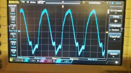
normally i do m frequency response with 400mVrms but its not possible because the signal gets deformated.
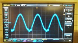
input is 300mVrms :
pic 1
measurement at the output of the first opamp pin 1 after the 10µF input cap
deformation in the negative sine wave.
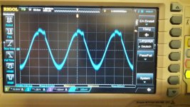
pic 2
measurement at the output of the first opamp pin 7 - its after the opamp 1 so its inverted and the deformation is not in the negative sine - its in the positive sine
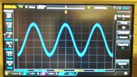
pic 3
measurement after the input caps- so signal is ok. i try up to 500mVrms and the signal form is ok.
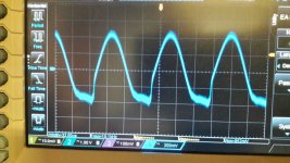
pic 4
signal at 15kHz is harder deformation
any ideas?
chris
Hi
normally i do m frequency response with 400mVrms but its not possible because the signal gets deformated.
input is 300mVrms :
pic 1
measurement at the output of the first opamp pin 1 after the 10µF input cap
deformation in the negative sine wave.
pic 2
measurement at the output of the first opamp pin 7 - its after the opamp 1 so its inverted and the deformation is not in the negative sine - its in the positive sine
pic 3
measurement after the input caps- so signal is ok. i try up to 500mVrms and the signal form is ok.
pic 4
signal at 15kHz is harder deformation
any ideas?
chris
Attachments
Yes, same here. Whatever equipment I use, above a certain level my neighbours make stress.

that is not what i mean....
i have my listening room in the cellar...and no neighbors
to be honest- for listening no problem...never the less i want to know whats happend:
i measured the input and the output voltage during normal listening with good music...no bumm bumm music
the music does n´t exceed more than 190mVrms input (normally about 100-130Vrms)and
24Vpp output on the terminal at 4ohms
its actually not 31V psu like in my lab - psu for listening is set to 28V
Ppeak = Vpp ^2 / 2 *R
Ppeak = 24V ^2 / 2*4
Ppeak = 576 / 8
72 watt peak
obviously you measured with ac-coupling. Whenever s.t. distorts asymmetrically it is a good idea to measure with dc coupling to see whether the bias voltage is correct or not.
Another hint: When you have found the first occurence of a failure, here at the first OPA-output, there is no point in investigating the following stages, these will not "autocorrect" any preceeding error.
Another hint: When you have found the first occurence of a failure, here at the first OPA-output, there is no point in investigating the following stages, these will not "autocorrect" any preceeding error.
Last edited:
obviously you measured with ac-coupling. Whenever s.t. distorts asymmetrically it is a good idea to measure with dc coupling to see whether the bias voltage is correct or not.
Another hint: When you have found the first occurence of a failure, here at the first OPA-output, there is no point in investigating the following stages, these will not "autocorrect" any preceeding error.
thanks you for the hints
the second sentence i understand
can you please explain the first?
why with DC coupling? which value should be ok?
tomorrow evening i will try...
chris
measurement at the output terminal.. both L+R have the same signal form.
at the other board i had´t this signal.
any constructive ideas??
I was getting the same type of glitching on both + and - peaks of the waveform when I fitted the pffb components to my pcb.. it turned out the output filter inductors were electromagnetically inducing pulses into the pffb feedback tracks on the underside of the board so I ditched my pffb circuit until I do revision 3 (if that ever happens lol).
I was getting the same type of glitching on both + and - peaks of the waveform when I fitted the pffb components to my pcb.. it turned out the output filter inductors were electromagnetically inducing pulses into the pffb feedback tracks on the underside of the board so I ditched my pffb circuit until I do revision 3 (if that ever happens lol).
Thanks for sharing your ideas.
i had the sine wave at the opamp.
i do not know if the YJTPA3255 china boards are set with PFFB.
If you measure DC coupled you see the DC bias as well, that is the DC voltage of the OPA output where the AC signal is centered. If it distorts on the neg excursion possibly this bias is to close to neg supply voltage.
The best option seems to me if you measure the DC voltage of each OPA pin (1..8) with a multimeter, w/o any AC input and show the results here.
The best option seems to me if you measure the DC voltage of each OPA pin (1..8) with a multimeter, w/o any AC input and show the results here.
Last edited:
In that case OPA pins 1-3 and 4-7 should be centered around +14V
at this board the LM2575S is regulating the psu voltage to appr. 15V for the LM317 -->
at the YJ board TPA3255 its the LM317 which provides the voltage of the opa´s
and therefore the max input for the tpa3255 chip (13.2V acc. Datasheet) at this board its set to 12,75V
sybic changed the setting of the LM317 to exactly 12V.
i did this for one board but the others not-because its in the tolerance-therefore its 12,75 /2 = 6,375V
sybic changed the 10k resistors at the opa´s from less tolerance (original is 10%...bad) to better tolerances 1% or better.
can the tolerances of the 10k resistors of 1 opa so weak that I do not get the Gain of 1 (Buffer) if i do not change the resistors to better tolerances?
and therefore the neg sine is cutted?
If you measure DC coupled you see the DC bias as well, that is the DC voltage of the OPA output where the AC signal is centered. If it distorts on the neg excursion possibly this bias is to close to neg supply voltage.
The best option seems to me if you measure the DC voltage of each OPA pin (1..8) with a multimeter, w/o any AC input and show the results here.
measured with my DMM
DMM -- OPA Voltage at pin 1,2,3 is PIN 5,7 = 6,03V
measured with scope/DC setting
DC with Scope shows OPA Voltage at pin 1,2,3 is PIN 5,7 = 6,15V
but in both cases
PIN 6 is not measurable --> Amp switch off if I put the probe there !!!????
additionally i discover a other version of blue board (blue V2)
V1
at the old board its the LM2575S with the LM317 an the place for AMS117-3,3 was empty
V2
now its other way round
LM2575T -12 - Set to 12,06 Volt - no LM317 but the AMS117-3,3 is on board
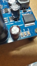
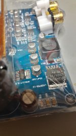
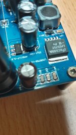
pic 1 old board -version 1
pic 2 new board - original packed blue V2
pic 3 new board -blue V2- my AMP5 with the muse input caps
so there is a small improvement - no setup of LM317 is needed
Attachments
at the blue boards with LM2575S and LM317 with out changes i measure 12,75 V+ at the LM317 --> opamps V+
measured with scope/DC setting
DC with Scope shows OPA Voltage at pin 1,2,3 is PIN 5,7 = 6,37V
here is the same
PIN 6 is not measurable --> Amp switch off if I put the probe there !!!????
fault LED
measured with scope/DC setting
DC with Scope shows OPA Voltage at pin 1,2,3 is PIN 5,7 = 6,37V
here is the same
PIN 6 is not measurable --> Amp switch off if I put the probe there !!!????
fault LED
additionally i discover a other version of blue board (blue V2)
LM2575T -12 - Set to 12,06 Volt - no LM317 but the AMS117-3,3 is on board
so there is a small improvement - no setup of LM317 is needed
Any link to blue V2 board, please.
looks like your amp is oscillating when measuring pin 6 (inv input B). Be sure your probe is set to 1:10 and NOT to 1:1.
hi
yes its a diff probe set to 1/20
- Home
- Amplifiers
- Class D
- What is wrong with TPA3255?