first impression of the new LC output filter:
compared to my TPA3251EVM its nearly so dark,deep, quiet, deep and smart as the TI amp. what i really like is the swing in and swing out of the instruments and voices of both boards.
I try to explain:
with this mod the sound stay in the background where it should be. the sound is not "jumping" from the middle back to the front.
now its from very back and stays there where e.g. the singer or instruments give its influence to the all others. = more holographic = life
chris
Last edited:
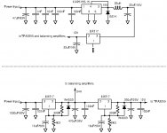
Chris, the Doctor, Think and many other did an impressive job in analyzing and proposing modifications of the “TPA3255 blue board” sold on Ebay, Amazon, AliExpress etc. Chris made me aware of the LM2575(HV)S problem so I started drawing up the low-power part of the board circuit. Schematics are appended to this posting.
The onboard power supply is made up of a Buck converter, stepping the input voltage down to just above 15V, followed by a linear LM317 regulator taking the voltage down to just above 12V with reduced ripple. The reason for the Buck converter is that the 12V consumption is above 100mA.
My concerns:
* I do not really appreciate an SMPS on a board with a high performance audio chip.
* The Buck output capacitor is 22uF rated at 16V (15.5V output voltage) and of an ordinary SMD type – not good for reliability.
* The 12V is also used for the input balancing circuit amplifiers (creating counter-phase). Not much voltage for the OP-AMPS.
* As Chris told me, the Buck IC is not the right LM2575HVS type handling 50V but only the ordinary 40V version.
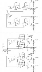
When I studied the input amplifier circuit, I noticed the amplifiers were based on TL072 OP-AMPS. Not really state-of-the art compared to the TPA3255. The input and output signal coupling capacitors were of the standard SMD 22uF/16V electrolytic type. Not recommended for quality audio use. Last, as mentioned above, the OP-AMPs were operated at only 12V total – not much and not allowing the best THD performance for high-performance OP-AMPs.
So, I removed all the bigger SMD components and implemented a new voltage regulator circuit and input amplifier circuit (shown below the dotted lines in the schematics). Cascaded LM317 linear regulators (24V and 12V outputs) and LM4562 based amplifiers operating from 24V. I arranged it all on a board put as a new input stage, and turned the power on – absolutely no sound!
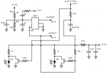
The reason was that the /RESET signal to the TPA3255 chip was affected when I removed the main components of the 15V SMPS. I drew up a schematic of the control circuit (more-or-less correct) and realized a very small 5pin IC (marked with “ARK” only) in a SOT-23-5 housing, just before the /RESET input. For a start, I believed this to be a micro-power 5V-to-3.3V LDO but it isn’t. The output voltage follows the input voltage. What exact purpose it serves here, I do not know. And, the input voltage divider (10K/3K6) divided the 12V voltage such that the voltage at the /RESET input was above 4V. The /RESET input is a 3.3V input that as absolute maximum can take 4.2V! There was a voltage stress problem here.
I put a 12K resistor in series with the 10K and connected it to my 24V supply line (resulting in 3.4V at the /RESET input). Then the amplifier worked.
How did it finally sound? - great. I could not compare with a circuit I had disassembled two days before but at least it sounds really good. The heatsinks get a bit warm but a slow-running fan brings them back to 30 degrees.
Amplifier boards, originating from the far east, normally follow the datasheet reference circuit quite closely. That is fine. When the designer has to improvise outside of the datasheet and application notes, the result deserves a critical look. Sometimes the implementation is fine – sometimes less well designed. It is of course a matter of price.
Finally, I learned about an electro-acoustic effect. When I modify amplifiers more profoundly, I do not bother about what is left and right, or phase, before at the end. For a start, I connected the amplifier without bothering about left, right and speaker phase. The amplifier had a nice deep bass kick. Then, I tested it with a left-right-phase mp3 and realized that left and right had to be swapped. It seemed also for the speaker phasing (tested on stereo perspective). New tests did not give the same convincing deep bass performance. I had about 2 meters between my speakers. The reason for the less good bass performance is described in this link: Online Stereo Polarity (Phase) Sound Test. I had simply swapped to counter-phase and my tests with very low frequencies just made one speaker absorb the bass sound waves generated by the other.
The onboard power supply is made up of a Buck converter, stepping the input voltage down to just above 15V, followed by a linear LM317 regulator taking the voltage down to just above 12V with reduced ripple. The reason for the Buck converter is that the 12V consumption is above 100mA.
My concerns:
* I do not really appreciate an SMPS on a board with a high performance audio chip.
* The Buck output capacitor is 22uF rated at 16V (15.5V output voltage) and of an ordinary SMD type – not good for reliability.
* The 12V is also used for the input balancing circuit amplifiers (creating counter-phase). Not much voltage for the OP-AMPS.
* As Chris told me, the Buck IC is not the right LM2575HVS type handling 50V but only the ordinary 40V version.
When I studied the input amplifier circuit, I noticed the amplifiers were based on TL072 OP-AMPS. Not really state-of-the art compared to the TPA3255. The input and output signal coupling capacitors were of the standard SMD 22uF/16V electrolytic type. Not recommended for quality audio use. Last, as mentioned above, the OP-AMPs were operated at only 12V total – not much and not allowing the best THD performance for high-performance OP-AMPs.
So, I removed all the bigger SMD components and implemented a new voltage regulator circuit and input amplifier circuit (shown below the dotted lines in the schematics). Cascaded LM317 linear regulators (24V and 12V outputs) and LM4562 based amplifiers operating from 24V. I arranged it all on a board put as a new input stage, and turned the power on – absolutely no sound!
The reason was that the /RESET signal to the TPA3255 chip was affected when I removed the main components of the 15V SMPS. I drew up a schematic of the control circuit (more-or-less correct) and realized a very small 5pin IC (marked with “ARK” only) in a SOT-23-5 housing, just before the /RESET input. For a start, I believed this to be a micro-power 5V-to-3.3V LDO but it isn’t. The output voltage follows the input voltage. What exact purpose it serves here, I do not know. And, the input voltage divider (10K/3K6) divided the 12V voltage such that the voltage at the /RESET input was above 4V. The /RESET input is a 3.3V input that as absolute maximum can take 4.2V! There was a voltage stress problem here.
I put a 12K resistor in series with the 10K and connected it to my 24V supply line (resulting in 3.4V at the /RESET input). Then the amplifier worked.
How did it finally sound? - great. I could not compare with a circuit I had disassembled two days before but at least it sounds really good. The heatsinks get a bit warm but a slow-running fan brings them back to 30 degrees.
Amplifier boards, originating from the far east, normally follow the datasheet reference circuit quite closely. That is fine. When the designer has to improvise outside of the datasheet and application notes, the result deserves a critical look. Sometimes the implementation is fine – sometimes less well designed. It is of course a matter of price.
Finally, I learned about an electro-acoustic effect. When I modify amplifiers more profoundly, I do not bother about what is left and right, or phase, before at the end. For a start, I connected the amplifier without bothering about left, right and speaker phase. The amplifier had a nice deep bass kick. Then, I tested it with a left-right-phase mp3 and realized that left and right had to be swapped. It seemed also for the speaker phasing (tested on stereo perspective). New tests did not give the same convincing deep bass performance. I had about 2 meters between my speakers. The reason for the less good bass performance is described in this link: Online Stereo Polarity (Phase) Sound Test. I had simply swapped to counter-phase and my tests with very low frequencies just made one speaker absorb the bass sound waves generated by the other.
Attachments
Concerning your concernsMy concerns:
* I do not really appreciate an SMPS on a board with a high performance audio chip.
* The Buck output capacitor is 22uF rated at 16V (15.5V output voltage) and of an ordinary SMD type – not good for reliability.
* The 12V is also used for the input balancing circuit amplifiers (creating counter-phase). Not much voltage for the OP-AMPS.
* As Chris told me, the Buck IC is not the right LM2575HVS type handling 50V but only the ordinary 40V version..
* A small buck regulator with a proper pcb-layout is not a big problem. Dr.Mord and me use these from the beginning of our TPA325x boards, and never found artifacts in our high-resolution measurements.
* Agreed, I would propose some 25V-SMD-cap
* 12V should be enough. Keep in mind the voltage level to drive TPA-3255 into clipping is less than 5Vpp each input.
* agreed, LM2575 is a "budget choice".
* TL072 is often underrated by audiophiles, it is not that bad.
But also this is a typical "budget choice".
* Electrolytic caps are fine in the audio path - they definitely do NOT alter the sound. Anyway I do not like their smd variants, soldering / de-soldering them is a nightmare.
I agree the chinese most of the time try to copy the reference design, which is not bad at all. Afterwards they "modify" them to save money - often with little knowledge of the drawbacks following these modifications. Thus developped this sport of buying cheap chinese boards just to pimp them up afterwards. Obviously this is fun for the crowd involved as well for spectators of that game.
")
Thank you for your comments.
I have seen some constructions you and the Doctor (mord!!?) are apparently behind. I know you are very competent people.
I admit that the Buck converter is a logical choice with a voltage drop of 30-40V and a current above 100mA. The feeling of mixing low noise signals with power square-wave signals does not appeal to me. But, the TPA3255 also uses power square-wave signals and the amplifier anyway has an output filter before the speakers.
The TL072 was a star some 20 years ago. Today, better can be found for a low price as well. NE5532 is an example.
I use attenuators on the outputs of my OP-AMPs in order not to exceed the 7Vpp maximum input to the TPA3255. It is not that I believe 12V is not sufficient to drive the TPA3255 inputs to the limits. I noticed from the LM4562 datasheet that little supply voltage leaves less good THD performance, due to the reduced bias currents I assume. Above +/- 12V there is little to gain.
You are the first serious and competent person I see stating that ordinary electrolytic capacitors in the signal path do not change the sound. Decades of teaching alleged such electrolytic capacitors to be non-linear and the source of noise. Why do we else buy more expensive audio-grade electrolytics when we can't find space for foil capacitors?
A question, do you happen to know what this small chip in the SOT-23-5 housing is good for?
Yes, the “pimp an Asian board”-game is great fun and good teaching with these prices. SMD components are difficult to handle without a PCB.
Thanks for your reaction, FF
Good evening;
I've received today tpa3255 by nobsound;https://images-na.ssl-images-amazon.com/images/I/51HaX56co8L._SX355_.jpg
I would to ask you, if this board sounds worse than TI evaluation board or the e3 boards and then (sorry for the idiot question), i read from tech specs
Total Output Power at 10%THD+N 185-W Stereo into 8 Ω in BTL Configuration
Total Output Power at 1%THD+N 150-W Stereo into 8 Ω in BTL Configuration
but..how can I choose to use the chip at 1% thd?
Thank you
Last edited:
The last question first: When you reduce the output power below 150W (8 Ohm), the THD is lowered very rapidly by itself. Just reduce the output power.
The blue board from Nobsound is very good but probably not as well implemented as the evaluation board from TI, which is more expensive. I only have the Nobsound board.
The blue board from Nobsound is very good but probably not as well implemented as the evaluation board from TI, which is more expensive. I only have the Nobsound board.
TL072 is a bit noisy, I would not use it in sensitive applications.For my knowledge there is no evidence of any nonlinear behaviour in electrolytics so I really do not see the point in "audio grade" electrolytics.
I do not have any of these PCBs, so I cannot comment on that SOT23-5.
I do not have any of these PCBs, so I cannot comment on that SOT23-5.
Thank you very much FauxFrench and voltWide
So I have to reduce DC power..now I have 44 volts..
Please check what is printed on the rather big IC with 5 pins in one end, located to the very left seen from the input side of the board. The printing should be "LM2575HVS" but on many boards it only says "LM2575S". If you have the "LM2575S", the supply voltage should be below 40V.
It is not the supply voltage you have to reduce to have lower THD, it is the input signal voltage (AC signal) and with that the output voltage (AC signal) and output power.
It is like with your car, if you drive it at maximum speed it makes a lot of noise. To lower the noise, you just reduce the speed a little by pressing the speeder less down.
With the IC being an LM2575S, do not use more than 40V supply, preferably up to 37V.
Yes, you reduce the AC input by turning the volume down.
The THD values of 1% and 10% you refer to are actually not operations that will be used in practice. Any amplifier becomes strongly non-linear close to what we call the "clipping level". 1% THD is very close to where the clipping starts and 10% clipping means solid clipping. These two values indicate the absolute maximum output power that can be squeezed out of the amplifier. Just like the 220Km/h maximum speed of a car - in theory it can do it but you won't use it.
10% THD sounds awful and in practice you will use some 1-10W at a THD of 0.01-0.05%.
Last edited:
The SOT23-5 is most likely the voltage supervisor IC which cares for RESET and undervoltage-lockout that mutes the amp before the power rails collapse. I don't like the EVMs implementation using capacitive voltage dividers due to the fact that they sometimes glitch "in the wild".
So instead, you recommend the circuit modification you posted last month? -I don't like the EVMs implementation using capacitive voltage dividers due to the fact that they sometimes glitch "in the wild".
http://www.diyaudio.com/forums/class-d/287470-tpa3255-diy-discussion-design-etc-73.html#post5488402
...pop sound...
actually i am not changed the pop on/off circuit from doctor, but....
is there any disadvantage if i use just the easy switch ???
post #726 page 73
http://www.diyaudio.com/forums/class-d/287470-tpa3255-diy-discussion-design-etc-73.html#post5488402
thanks
cu
actually i am not changed the pop on/off circuit from doctor, but....
is there any disadvantage if i use just the easy switch ???
post #726 page 73
http://www.diyaudio.com/forums/class-d/287470-tpa3255-diy-discussion-design-etc-73.html#post5488402
thanks
cu
- Home
- Amplifiers
- Class D
- What is wrong with TPA3255?