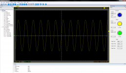
Here are the measurements:
- 250kHz - Uout=1,750V rms;
- 400kHz - Uout=0,700V rms;
- 470kHz - Uout=0,500V rms.
The input is shortened. For load I used 5 ohm - two 10 ohm 2W resistors in parallel.
The supply voltages are +/-58V from 300W transformer and 2x10000uF capacitors.
The measurements are made with USB oscilloscope Hantek 6022BE, not modded and with the original PC software.
The trimpot is for setting the frequency, above are listed the possible limits.
The green probe is shortened, to show the oscilloscope's self noise...
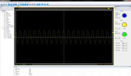
Attachments

Last edited:
I would have thought you could put R29 right up level with R31. Looks to be enough space between where the mosfet plastic body ends and it's gate pad starts. Same with the other side.
Well, in the production you will want to keep a certain distance from SM and TH parts because of the different soldering process. In a that close proximity to the TH the contact pad, solder and likely the glue for the SMD resistor (not the resistor itself) would be reheated and possibly damaged, creating a stress point and therefore making it a likely point of failure. To move it away is a logical step and they've placed it to the next nearest possible location while keeping a straight path and gives more tolerance for the soldering of the TH parts. That does not seem to be a that bad solution.
Could that have been changed? Probably. Would it improve the performance? I don't know, maybe, maybe not, that depends on how the amp performs the way it is. I would suppose it's not an issue though.
To get us back on topic, a year ago in diy-hifi-forum.eu there was Saarmichel hooraying a 500W Chinese amp module, a small board with a heatsink and a fan, meant for a supply around +-50V. Lately another also more or less professional member measured it and found out, that it outputs maximum power for only small fractions of a second and limits constant power to 200W or even less. You can read it up, search for Gremlin.
There are no parts in this PCB to do this function actively. This limiting comes from a sum of factors: current limting in IR gate drivers is implemented by sensing FET Vds-on, FETs have 2x the Rds-on at 125C w.r.t. 25C, and rails sag. But FETs take more than a fraction of a second to get hot, the copper tab in a TO-220 tab takes about 100W losses for 1 second to rise by 100C, and with audio full power operation is in bursts only.
To get us back on topic, a year ago in diy-hifi-forum.eu there was Saarmichel hooraying a 500W Chinese amp module, a small board with a heatsink and a fan, meant for a supply around +-50V.
It is about the Sure TAmp 2500/AA-AB32512 and other members of the same amp family. +-50V is wrong though, they do not run with symmetrical power supplies, they are single ended only.
Lately another also more or less professional member measured it and found out, that it outputs maximum power for only small fractions of a second and limits constant power to 200W or even less. You can read it up, search for Gremlin.
The thread can be found here (German), the test can be found here (PDF), he didn't mention the amplifier model in the test (it was the Sure AA-AB32512), he did not mention the specs of the power supply (other than 'toroidal transformer'), so no voltage, no current or filter capacitance given, that makes the 'lab report' rather unprofessional. Someone else later mentioned the PS was only 30 VAC, 500 VA - which translates into 42V DC while the amp needs 50V for full power, and the measurement was taken at 1%THD while the claimed 500W would be at 10% THD, so a lot lower maximum power is to be expected in any case.
If you want to make something look bad, it is very easy to do so by just leaving out informations or playing with the rules of the measurement. For the circumstances, the measurements are completely okay. However, one would not expect the amp to achieve the full 2x500W either.
If you need speakers protection, I believe that you are using underpowered speakers.
With a lot less than the maximum speaker power you can easily kill tweeters with clipping. And DC can damage the the voice coil severely if it hits the back pole plate - also with a quite small amp and at high power capable speakers.
I am sure someone will tell me otherwise but they usually use relays and that type of electromechanical component is likely to fail long before the amp or the speaker.
The protection relays got an extremely easy life because they have to very rarely switch and even much rarer with full load. I have amps that are 40 years old and the original relays still work perfectly. One does not expect every relay to live that long but they have a very long life expectancy.
From Gremlin (Sure) - kleiner Laborbericht - DIY-HIFI-Forum :If you want to make something look bad, it is very easy to do so by just leaving out informations or playing with the rules of the measurement. For the circumstances, the measurements are completely okay. However, one would not expect the amp to achieve the full 2x500W either.
Translation: Measuring with a log sweep, the amp shuts down yet with half input voltage. ... It loves lo freqs neither. Current limiting (editor means, not necessarily current limiting, it might also be temp limiting, as Eva thinks) hits immediately.Wenn man den Verstärker mit einem logarithmierten Sweep messen will quittiert er bereits bei halber Eingangsspannung die Ausgabe. Er macht sofort zu und will nur kurzzeitig belastet werden. Das Problem haben aber sehr viele Chipamps. Tiefe Frequenzen mag er auch nicht besonders gern. Die Strombegrenzung setzt dann schlagartig ein.
Half voltage is quarter power. And that is yet with a smaller supply so smaller max output power. So is it 500W peak 50W sine? For the thread starter's purpose the question matters.
Saw this tiny 500W amp board on Ebay.
IRS2092S 500W Mono Channel Digital Amplifier Module Class D HIFI Power Amp Board | eBay
Are the figures for this general type of amp even believable, or are they a total exaggeration? Thinking of using a pair to drive a pair of 15" subs in relatively small sealed boxes with a Linkwitz transform equaliser. Not to a very high sound level but I expect the overall efficiency will be down the toilet. Also thinking of experimenting with 3 boards as a low voltage 3-phase AC source for driving a motor. Just for fiddling around, nothing practical.
So... is this kind of board worth the trouble?
I had a similar moment a couple of years ago and now I've a couple of the Sure class d boards.
If you want one you can have it - pm me and we can work out the details.
...I intended it for some subs and never got around to the sub building bit. So the board is surplus.
Translation: Measuring with a log sweep, the amp shuts down yet with half input voltage. ... It loves lo freqs neither. Current limiting (editor means, not necessarily current limiting, it might also be temp limiting, as Eva thinks) hits immediately.
That's ofcourse true. It depends on the use if that makes an amp good or bad. And that's why the judgements differ by so far if a particular class-D amp is suited for something or not, so much more difficult than saying if any class AB or H amps are fit for the need.
Half voltage is quarter power.
Well, that only applies if the power supply isn't current restricted on the higher voltage.
And that is yet with a smaller supply so smaller max output power. So is it 500W peak 50W sine? For the thread starter's purpose the question matters.
That's exactly the question, that really matters. If you want really high power and don't need the light weight, it's often better to get a second hand (real) PA amp, with around 80-150 bucks you can get 2x500W or more and these amps are mostly real workhorses, reliable and safe.
What i was searching was not in the forum...
Amazon.com: WinnerEco IRS2092S 500W Mono Channel Digital Amplifier Class D HIFI Power Amp Board: Computers & Accessories
I ordered two of these and when I received them they would only oscillate and heat up and make garbage. After asking the seller for some assistance, that I guess they couldn't offer as they just refunded my money,I looked the boards over and noticed that r13 was the wrong value. It should of been somewhere above 3k as it is part of a resistor pair that sets the gain, but was only 100 ohms, and so I was getting a gain of 300+ instead 39 or so. So I replace it with a 4k7 1206 resistor and all is well. The gain is a little low but it's what I had on hand. Surprisingly I believe it could actually do 500 watts, and I will test it. I did 250 watts into a 5 ohm resistor and it held up well. 5 minutes of 1khz tone at 250 watts, not bad.
Half voltage is quarter power.
Well, that only applies if the power supply isn't current restricted on the higher voltage.
Isn't it just Ohms law?
Isn't it just Ohms law?
It's not 'just' Ohms law because of a. the voltage drop in the semiconductors (if you want a precise result) and b. the current limit of the amp itself. So if b. applies that means no, you can't just take the value of the power at voltage x and multiply/divide for voltage y.
which DIP8?
Great minds? Do you know what SO-8 they used for the 12V? Potential issue with upper bias holding long enough for low frequencies, same as UCD.
BTW the first circlotron I discovered was a UDCO water cooled 30KW shake table amp in 3 racks; got replaced with class-D IGBTs in one rack, both powered by 480V 3-phase.
In the process of developing this tiny module someone discovered that a switching regulator SO-8 IC can be used to obtain the gate drive supply rail for IRS2092, referred to -Vcc, and by the way used those 12V to power a fan, maybe even temperature switched with a transistor and NTC.
Great minds? Do you know what SO-8 they used for the 12V? Potential issue with upper bias holding long enough for low frequencies, same as UCD.
BTW the first circlotron I discovered was a UDCO water cooled 30KW shake table amp in 3 racks; got replaced with class-D IGBTs in one rack, both powered by 480V 3-phase.
Last edited:
")
- Home
- Amplifiers
- Class D
- Ebay amp - is 500W believable?