Hi,
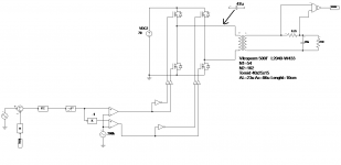
i'm testing an inverter with these features:
Fswitching=220KHz
Fout=3KHz-10Khz
Vout=150Vac
Pout=150W
Current feedback.
Sinusoidal output is obtained with transformer leakage inductor+output capacitor.
In the figure below there is the schematic.

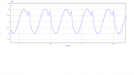
The problem is that a little DC component (about 100mA) put transformer into saturation and the output waveform has a distorsion as in figure

I don't understand from where it can come this DC component. Could you help me?
A capacitor could solve my problem? what features should have this capacitor? Ceramic or film cap? I had thought of 47uF@25volt as the voltage across it should never be too high.
Let me know.
i'm testing an inverter with these features:
Fswitching=220KHz
Fout=3KHz-10Khz
Vout=150Vac
Pout=150W
Current feedback.
Sinusoidal output is obtained with transformer leakage inductor+output capacitor.
In the figure below there is the schematic.

The problem is that a little DC component (about 100mA) put transformer into saturation and the output waveform has a distorsion as in figure

I don't understand from where it can come this DC component. Could you help me?
A capacitor could solve my problem? what features should have this capacitor? Ceramic or film cap? I had thought of 47uF@25volt as the voltage across it should never be too high.
Let me know.
So you are trying to push a PWM signal through a transformer?
The transformer would have to not saturate at the lowest "equivalent" frequency of the PWM signal (extreme duty cycle) at the peak voltage.
What happens when you go to 1KHz?
What happens when you reduce amplitude the 3KHz-10KHz signal?
Make a plot of the low frequency component (1KHz-10KHz) of frequency vs amplitude at a set distortion level.
Should be interesting.
- Status
- This old topic is closed. If you want to reopen this topic, contact a moderator using the "Report Post" button.